
DNP3 implementations vary widely between different equipment manufacturers. Before configuration of an application using the VTScada DNP3 driver, be sure to review the specific DNP3 implementation of your devices.
With release 12.1.39 of VTScada, the driver behavior has changed in the following ways for new applications. This behavior is controlled by the new property, DNP3DefaultNoScan. New applications have this property set to 1, whereas existing applications will have it undefined, which is the same as 0.
Addresses without a suffix
Polling will be event-based, unless the object itself does not support events, such as Time and Date, File Transfer.
New data is returned by Class polling or unsolicited messages whenever the value in the device changes beyond the constraints of deadband and de-bounce settings.
Addresses with :DR
Will use the standard VTScada interval-based polling, returning the current value of the point.
Addresses with :NS
Treated the same as addresses with no suffix.
For existing applications, addresses without a suffix will always use standard polling. To use event-based polling, :NS is required.
Addresses that do not support events will return an error if a suffix is added. Standard polling will always be used.
Within VTScada, DNP I/O addresses for all points except File Identifiers (object 70) are formatted in the following manner:
Obj/Var/Index[:NS | :LATCH | :PULSE]
Where:
- Obj is the DNP object to use. A table of supported object types can be found later in this topic.
- Var is the DNP variation of the object
- Index is the points index. For the Restart flag in the Internal Indications (object 80, var 1) use an index of 7.
- :NS is used to stop direct polls of the I/O address. DNP3 events and Class 0 Integrity polls will update the tag value regardless of the presence or absence of the :NS suffix. Note that DNP3 works most efficiently without direct polls.
- :LATCH is used to indicate the output type is a latched control.
- :PULSE is used to indicate the output type is a pulsed control. Use only with I/O tags with the data type set to Analog.
VTScada provides the DNP 3.0 Address Select dialog (Address Assist / Address Select) to help you build these addresses. In any tag that uses a DNP3 driver, the I/O panel of the configuration dialog will provide a button beside the Address field:
The Address Select will help you build an address, but you are not restricted by its available options. As long as the address field contains a valid, indexed address, VTScada will pass the data along. You can use the Address Select tool, or type out a known address manually, or start with the Address Select and modify the result.
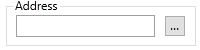
Click this to open the Address Select dialog.
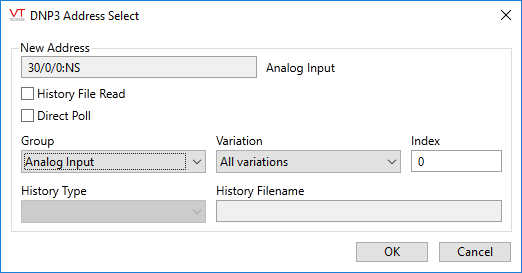
VTScada's DNP3 Address Select can auto-generate an object number representing tag type groups.
In the Group droplist, select the tag type group designation of your IO tags.
Available groups include:
- Binary Input
- Binary Output Status
- Counter
- Frozen Counter
- Analog Input
- Analog Output Status
- Time and Date
- Internal Indications
- Octet String
If the Direct Poll option is not selected, then (for the appropriate groups) the suffix :NS will be added to the address and no variations may be applied.
Click the Direct Poll option to allow scanning and to enable the Variation selector, the content of which will vary according to the selected Group.
Binary Output:
Devices may use one of three control models:
- Activation Model. A single signal. The output is activated for the duration of the on-time regardless of the code being sent.
- Complementary Latch Model. A single output signal that is held at the commanded state.
- Complementary Two-Output. Two outputs named close and trip. One or other output is set active momentarily for a commanded on-time and off-time.
The VTScada output address suffixes, :Latch, :Pulse, or no suffix indicating a Trip/Close control, relate to these models as follows:
For the following, the term "on-time" refers to the duration of the signal, not the value or control code sent in the signal.
By the DNP3 specification, timings are suggestions. The device may use the supplied timing, may limit the supplied timing to its own configured limits, or may substitute timing with its own configured values.
The suffix :LATCH should not be confused with the Complementary Latch Model of control.
To send an exact value of zero (0) or one (1), a Digital Control or Digital Output tag is recommended. To send any other value, use an Analog Control or Analog Output tag.
Trip/Close control (Analog types only. No suffix added to the address)
Use only with Analog Control or Analog Output tags. Values greater than zero send a close request (control code 0x41) and values equal to or less than zero send a trip request (control code 0x81).
The absolute value being written is the duration of the on-time, measured in milliseconds. Note that a value of zero, written by the tag, sends a trip request with an on-time of one millisecond. Scaling values must be set to allow the range of value that is being written, otherwise they will clamp the value.
- Activation Model: The output is set to active for the duration of the on-time.
- Complementary Latch Model: The output is set to active for a close (value > 0) or set to inactive for a trip (value <= 0).
- Complementary Two-Output Model: Either the close output is set to active if a close (value > 0) is sent, or the trip output is set active for a trip (value <= 0), for the duration of the on-time.
Examples:
1 - sends a close request with an on-time of 1 millisecond.
0 - sends a trip request with an on-time of 1 millisecond.
1000 - sends a close request with an on-time of 1 second.
-1000 - sends a trip request with an on-time of 1 second.
:LATCH suffix
The DNP3 standard does support sending an on-time and off-time for the latch on|off codes, but this driver does not when the :LATCH suffix is in use. It always sets the times to 0, so is likely to be useful only with a complementary latch module output.
A Digital Control or Digital Output tag is recommended.
A value greater than zero (1) sends a latch-on request (control code 0x03).
A value less than or equal to zero (0) sends a latch-off request (control code 0x04).
- Activation Model: The output is set to active.
- Complementary Latch Model: The output is set active for a latch-on and inactive for a latch-off.
- Complementary Two-Output Model: The output is set active for a latch-on and inactive for a latch-off.
Examples:
1 - sends a latch-on request.
0 - sends a latch-off request.
:PULSE suffix
Use only with Analog Control or Analog Output tags. The value to write should be a single value as shown in the examples, or else it must include both the pulse-on duration and the pulse-off duration in milliseconds, separated by a period. It is up to the RTU to hold the pulse for the specified durations - VTScada simply sends the information in one write. For example, to send an 8-second pulse control command to CROB #23, create an Analog Control tag with address 12/1/23:PULSE and use it to write a value of 8000 to the device.
Neither of the complementary models are supported.
Both an on-time and an off-time can be specified in milliseconds as follows. Given a numeric value, "nnn.fff"
- The absolute value of the digits preceding the decimal point (nnn) specifies the on-time in milliseconds.
- The absolute value of the digits following the decimal point (fff) specifies the off-time in milliseconds.
Positive values greater than zero (> 0) send a pulse-on request (control code 0.01).
Negative values (<= 0) send a pulse-off request (control code 0x02).
- Activation Model: The output is set active for the duration of the on-time.
- Complementary Latch Model: A "NOT-SUPPORTED" status will be returned.
- Complementary Two-Output Model: A "NOT-SUPPORTED" status will be returned.
Examples:
The following are values to write to an Analog Control tag:
1 - sends a pulse-on request with an on-time of 1 millisecond and an off-time of 0.
0 - sends a pulse-off request with an on-time of 0 milliseconds and an off-time of 0. This may cause an error as there should normally be some value for the on-time.
-1 - sends a pulse-off request with an on-time of 1 milliseconds and an off-time of 0.
5000.999 - sends a pulse-on request with an on-time of 5 seconds and an off-time of 0.999 seconds.
-4000.003 - sends a pulse-off request with an on-time of 4 seconds and an off-time of 3 milliseconds.
To set a point to use SBO rather than direct operate, append the suffix ":SBO" to the I/O address. The SBO suffix can be used in combination with the other output attribute suffixes, ":PULSE" or ":LATCH".
This suffix is available as an option in the DNP3 address assist dialog when building a binary output command.
Reads
Address examples for reading values:
To read a digital input with status (obj 1, var 2) at address 4321 use
1/1/4321.
To read a 32 bit delta counter without status (obj 20, var 7) at address 876 use
20/7/876
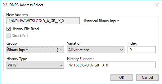
A History Read address takes the form G/V/INDEX:HW:FILENAME, where:
- G is the DNP3 "group", the supported groups are 1 (Binary Input), 10 (Binary Output status), 20 (Counter), 30 (Analog Input), and 40 (Analog Output Status).
- V is the DNP3 variation, for History Reads this should be 0 (all variations).
- INDEX is the point index.
- The ":H" suffix indicates a History Read.
- W is the history type, currently only WITS is supported so the type is "W".
- ":FILENAME" is the name of the history file to read. At time of writing, only the WITS global all points log file is supported. This has a filename of "WITSLOG\D_A_GB__X_X" which is the default.
An example of an actual WITS History Read address is:
"30/0/1:HW:WITSLOG\D_A_GB__X_X".
Outstation Directory Reads
Outstation directories may be read using an I/O address as follows:
70/5/DirectoryPath,READDIR
Where:
- DirectoryPath is the path to the directory to be read. This will vary by outstation.
The normal use for this will be from script via a Read command.
Example:
ReadObj = Variable("DriverName")\DriverRead("70/5//data,READDIR", 1, &Result)
ReadObj will go invalid on completion.
Result will be set to an 2D array of directory entries, one row for each entry where the columns are as follows:
[0] Entry name Either file name or a sub-directory name [1] Entry Type 1 for a file, 0 for a sub-directory [2] Entry size File length for a file, number of entries for a sub-directory [3] Timestamp UTC [4] Permissions* The permissions for the entry
* DNP3 File permissions are a set of 9 bits, indicating read, write and execute permissions for the user, group and world. Normally written in octal, the value 0777 is "all permissions for all classifications". The exact meaning of the bits is outstation-dependent.
DNP3 File Reads
Files may be read from the outstation using an I/O address as follows:
70/5/PathToFile
Where:
- PathToFile includes the path for the file. This will include forward slashes for directories. The exact path will depend on the outstation - see example.
Example:
ReadObj = Variable("DriverName")\Driver\Read("70/5//data/newdata.txt", 1, &Result)
The result will be available as a buffer when the ReadObj goes Invalid.
DNP3 File Writes
Files may be written to the outstation using an I/O address as follows:
70/5/PathToFile[,Timestamp[,Permissions[,Append]]]
Where:
- PathToFile includes the path for the file. This will include forward slashes for directories. The exact path will depend on the outstation - see example.
- The optional parameter, Timestamp, is the timestamp for the file on the outstation in seconds since 1/1/1970, UTC. The default is the current time of the I/O server (in UTC).
- The optional Permissions* are the permissions for the file. The default is 0777.
- Append is a flag indicating the behavior of the write if the indicated file already exists on the outstation. If TRUE, the file will be appended to. If FALSE, the file will be overwritten by the new data. The default is false (no append)
The normal use for this will be from script via a Write command.
Example:
WriteObj = Variable("DriverName")\Driver\Write("70/5//data/newdata.txt", 1, &FileStrm, Invalid, "SomeText", &Result)
Result will become valid after the file write has completed - TRUE for success, FALSE for failure. In addition, WriteObj will become invalid on completion.
FileStrm, the data to be written to the outstation file, can be a stream or a buffer. In the example given, the file to be written to is "/data/newdata.txt". The paths used will depend on the outstation.
DNP3 File Deletions
Files may be deleted from the outstation using an I/O address as follows:
70/5/PathToFile,DELETE
Where: PathToFile includes the path for the file to be deleted.
The normal use for this will be from script via a Write command.
Example:
WriteObj = Variable( "DriverName")\Driver\Write( "70/5//data/newdata.txt,DELETE", 1, &FileStrm, Invalid, "SomeText", &Result)
Note that some valid data must be provided as the data parameter (FileStrm) but it's contents are ignored.
DNP3 object types supported
Please refer also to the Implementation Table of the document, DNP3DeviceProfileApril2016.xslt, included with your VTScada program.
| Object Description | Object Type | Object Variation | Read | Write |
|---|---|---|---|---|
| Single bit binary input all variations | 1 | 0 | ✓ | |
| Single bit binary input | 1 | 1 | ✓ | |
| Single bit binary input with status | 1 | 2 | ✓ | |
| Single bit binary input event all variations | 2 | 0 | ✓ | |
| Single bit binary input event without time | 2 | 1 | ✓ | |
| Single bit binary input event with time | 2 | 2 | ✓ | |
| Single bit binary input event with relative time | 2 | 3 | ✓ | |
| Single bit binary output all variations | 10 | 0 | ✓ | |
| Single bit binary output status | 10 | 2 | ✓ | |
| Control relay output block | 12 | 1 | ✓ | |
| Binary counter all variations | 20 | 0 | ✓ | |
| 32 bit binary counter | 20 | 1 | ✓ | |
| 16 bit binary counter | 20 | 2 | ✓ | |
| 32 bit delta counter | 20 | 3 | ✓ | |
| 16 bit delta counter | 20 | 4 | ✓ | |
| 32 bit binary counter without status | 20 | 5 | ✓ | |
| 16 bit binary counter without status | 20 | 6 | ✓ | |
| 32 bit delta counter without status | 20 | 7 | ✓ | |
| 16 bit delta counter without status | 20 | 8 | ✓ | |
| Frozen binary counter all variations | 21 | 0 | ✓ | |
| Frozen 32 bit binary counter with status | 21 | 1 | ✓ | |
| Frozen 16 bit binary counter with status | 21 | 2 | ✓ | |
| Frozen 32 bit delta counter with status | 21 | 3 | ✓ | |
| Frozen 16 bit delta counter with status | 21 | 4 | ✓ | |
| Frozen 32 bit binary counter with time | 21 | 5 | ✓ | |
| Frozen 16 bit binary counter with time | 21 | 6 | ✓ | |
| Frozen 32 bit delta counter with time | 21 | 7 | ✓ | |
| Frozen 16 bit delta counter with time | 21 | 8 | ✓ | |
| Frozen 32 bit binary counter no status | 21 | 9 | ✓ | |
| Frozen 16 bit binary counter no status | 21 | 10 | ✓ | |
| Frozen 32 bit delta counter no status | 21 | 11 | ✓ | |
| Frozen 16 bit delta counter no status | 21 | 12 | ✓ | |
| Binary counter event all variations | 22 | 0 | ✓ | |
| 32 bit binary counter event without time | 22 | 1 | ✓ | |
| 16 bit binary counter event without time | 22 | 2 | ✓ | |
| 32 bit delta counter event without time | 22 | 3 | ✓ | |
| 16 bit delta counter event without time | 22 | 4 | ✓ | |
| 32 bit binary counter event with time | 22 | 5 | ✓ | |
| 16 bit binary counter event with time | 22 | 6 | ✓ | |
| 32 bit delta counter event with time | 22 | 7 | ✓ | |
| 16 bit delta counter event with time | 22 | 8 | ✓ | |
| Frozen binary counter event all variations | 23 | 0 | ✓ | |
| Frozen 32 bit binary counter event without time | 23 | 1 | ✓ | |
| Frozen 16 bit binary counter event without time | 23 | 2 | ✓ | |
| Frozen 32 bit delta counter event without time | 23 | 3 | ✓ | |
| Frozen 16 bit delta counter event without time | 23 | 4 | ✓ | |
| Frozen 32 bit binary counter event with time | 23 | 5 | ✓ | |
| Frozen 16 bit binary counter event with time | 23 | 6 | ✓ | |
| Frozen 32 bit delta counter event with time | 23 | 7 | ✓ | |
| Frozen 16 bit delta counter event with time | 23 | 8 | ✓ | |
| Analog input all variations | 30 | 0 | ✓ | |
| 32 bit Analog input | 30 | 1 | ✓ | |
| 16 bit Analog input | 30 | 2 | ✓ | |
| 32 bit Analog input without status | 30 | 3 | ✓ | |
| 16 bit Analog input without status | 30 | 4 | ✓ | |
| Float Analog input without status | 30 | 5 | ✓ | |
| Double Analog input without status | 30 | 6 | ✓ | |
| Analog input event all variations | 32 | 0 | ✓ | |
| 32 bit Analog input event without time | 32 | 1 | ✓ | |
| 16 bit Analog input event without time | 32 | 2 | ✓ | |
| 32 bit Analog input event with time | 32 | 3 | ✓ | |
| 16 bit Analog input event with time | 32 | 4 | ✓ | |
| Float Analog input event without time | 32 | 5 | ✓ | |
| Double Analog input event without time | 32 | 6 | ✓ | |
| Float Analog input event with time | 32 | 7 | ✓ | |
| Double Analog input event with time | 32 | 8 | ✓ | |
| Analog output all variations | 40 | 0 | ✓ | |
| 32 bit Analog output status | 40 | 1 | ✓ | |
| 16 bit Analog output status | 40 | 2 | ✓ | |
| Float Analog output status | 40 | 3 | ✓ | |
| Double Analog output status | 40 | 4 | ✓ | |
| 32 bit Analog output | 41 | 1 | ✓ | |
| 16 bit Analog output | 41 | 2 | ✓ | |
| Float Analog output | 41 | 3 | ✓ | |
| Double Analog output | 41 | 4 | ✓ | |
| Time and Date | 50 | 1 | ✓ | ✓ |
| Common Time Object | 51 | 1 | ✓ | |
| Common Time Object - unsynchronized | 51 | 2 | ✓ | |
| Time delay coarse | 52 | 1 | ✓ | |
| Time delay fine | 52 | 2 | ✓ | |
| Class 0 Event data | 60 | 1 | ✓ | |
| Class 1 Event data | 60 | 2 | ✓ | |
| Class 2 Event data | 60 | 3 | ✓ | |
| Class 3 Event data | 60 | 4 | ✓ | |
| File Identifier (older systems) | 70 | 1 | ✓ | ✓ |
| File Identifier (preferred object for newer systems) | 70 | 5 | ✓ | ✓ |
| Internal Indications object | 80 | 1 | ✓ | |
| Octet String | 110 | *(1) | ✓ | ✓ |
| Octet Change Object | 111 | *(2) | ✓ |
*(1) The variation in the I/O address is used to set the length of the string. If the string is shorter than the variation, it is right-aligned and padded with spaces to fit the variation.
The DNP3 driver allows the use of an additional suffix, ":SL" that overrides the variation with the length of the supplied string, thus allowing callers to pass in arbitrary strings and not have to modify the variation element of the I/O address. The ":SL" suffix is only valid for Octet string writes. Octet strings are limited to 0..255 bytes. Anything attempted outside this range will cause the driver to report an error.
*(2)Event\change objects would not normally be configured as I/O addresses. They are listed to indicate that processing support is provided them. Upon receiving an event\change object, the value of the corresponding static object will be updated. For example, if 110/255/6 is configured and an event is received for 111/13/6, then the tag reading the first address will be updated with the value from the event\change as they share the same index.
Static\event object pairs that obey this rule include:
- g1 Binary Input and g2 Binary Input change
- g10 Binary Output and g11 Binary Output change
- g20 Counter and g22 Counter change
- g21 Frozen Counter and g23 Frozen Counter change
- g30 Analog Input and g32 Analog Input change
- g40 Analog Output and g42 Analog Output change
- g110 Octet Strings and g111 Octet String change
Data values returned for the objects that may be read:
| Object Description | Return Value |
|---|---|
| Single bit binary input | 0 or 1. |
| Single bit binary input with status | If status is OK, 0 or 1, else invalid. |
| Single bit binary input event without time | If status is OK, 0 or 1, else invalid. Refer to the note following this table. |
| Single bit binary input event with time | If status is OK, 0 or 1, else invalid. Refer to the note following this table. |
| Single bit binary output status | If status is OK, 0 or 1, else invalid. |
| 32 bit binary counter | If status is OK, 32 bit unsigned integer, else invalid. |
| 16 bit binary counter | If status is OK, 16 bit unsigned integer, else invalid. |
| 32 bit delta counter | If status is OK, 32 bit unsigned integer, else invalid. |
| 16 bit delta counter | If status is OK, 16 bit unsigned integer, else invalid. |
| 32 bit binary counter without status | 32 bit unsigned integer. |
| 16 bit binary counter without status | 16 bit unsigned integer. |
| 32 bit delta counter without status | 32 bit unsigned integer. |
| 16 bit delta counter without status | 16 bit unsigned integer. |
| 32 bit binary counter event without time | If status is OK, 32 bit unsigned integer, else invalid. Refer to the note following this table. |
| 16 bit binary counter event without time | If status is OK, 16 bit unsigned integer, else invalid. Refer to the note following this table. |
| 32 bit delta counter event without time | If status is OK, 32 bit unsigned integer, else invalid. Refer to the note following this table. |
| 16 bit delta counter event without time | If status is OK, 16 bit unsigned integer, else invalid. Refer to the note following this table. |
| 32 bit binary counter event with time | If status is OK, 32 bit unsigned integer, else invalid. Refer to the note following this table. |
| 16 bit binary counter event with time | If status is OK, 16 bit unsigned integer, else invalid. Refer to the note following this table. |
| 32 bit delta counter event with time | If status is OK, 32 bit unsigned integer, else invalid. Refer to the note following this table. |
| 16 bit delta counter event with time | If status is OK, 16 bit unsigned integer, else invalid. Refer to the note following this table. |
| 32 bit Analog input | If status is OK, 32 bit signed integer, else invalid. |
| 16 bit Analog input | If status is OK, 16 bit signed integer, else invalid. |
| 32 bit Analog input without status | 32 bit signed integer. |
| 16 bit Analog input without status | 16 bit signed integer. |
| 32 bit Analog input event with time | If status is OK, 32 bit signed integer, else invalid. Refer to the note following this table. |
| 16 bit Analog input event with time | If status is OK, 16 bit signed integer, else invalid. Refer to the note following this table. |
| 32 bit Analog input event without time | If status is OK, 32 bit signed integer, else invalid. Refer to the note following this table. |
| 16 bit Analog input event without time | If status is OK, 16 bit signed integer, else invalid. Refer to the note following this table. |
| 32 bit Analog output status | If status is OK, 32 bit signed integer, else invalid. |
| 16 bit Analog output status | If status is OK, 16 bit signed integer, else invalid. |
| Time and Date | The current date and time in the outstation as a floating-point number representing the number of milliseconds since Jan 1 1970. |
| File Identifier | A buffer containing the records requested, or an individual value of the specified type from the specified offset in a specified record. |
| Octet String | A buffer containing the string. |
Note: For events, the return value is an array of five elements:
| Index | Element |
|---|---|
| 0 | The address of the point in the form Object/Variation/Address. |
| 1 | Value, after correction for any status flags. If the status is on-line, not restart and not communication lost, the value will be as reported in the event, otherwise the value will be invalid. |
| 2 | The timestamp of the event. |
| 3 | The actual value before correction for status flags |
| 4 | The status flags. |
For those events that return a time, the time will be as recorded in the device. For those events that do not return a time, the time will be the local time when the driver received the message.
Time values are returned as a double, representing the time as the number of milliseconds since midnight, on 1/1/1970.
The data values that may be supplied for output objects:
| Object Description | Data Value |
|---|---|
| Control relay output block | 32 bit signed integer. If > 0, then action will be a latch on, close or raise. The time for the raise will be the value supplied in units of milliseconds. If =< 0, then action will be a latch off, open or lower. The time for the lower will be the absolute value supplied in units of milliseconds. The Latch flag, if TRUE, will cause the output to be a latch type. |
| 32 bit Analog output | 32 bit signed integer. |
| 16 bit Analog output | 16 bit signed integer. |
| Float Analog output | IEEE Single Precision Floating (4 bytes) |
| Double Analog output | IEEE Double Precision Floating (8 bytes) |
| Time and Date | The data value is ignored. The current date and time of the VTScada system will be sent to the outstation. |
| File Identifier | A buffer containing the records to be written. |
| Internal Indications | 16 bit unsigned integer. Note that only certain values are allowed and will be detailed in the remote device's profile. |
Note to VTScada programmers who are using the DNP3 driver in their code:
The following flags are available in the VTScada layer of the driver and will be updated by every response from the remote station:
| Flag | Meaning |
|---|---|
| IINTimeSync | TRUE when Time sync is required by the Outstation. |
| IINLocalDO | TRUE when some DO's in the Outstation are in local control. |
| IINTrouble | TRUE when an abnormal condition exists in the Outstation. |
| IINRestart | TRUE when an Outstation restart has occurred. |
| IINEventOverflow | TRUE when Outstation event buffers have overflowed. |
| IINConfigCorrupt | TRUE when Outstation configuration is corrupt. |
