Reference Boxes and Scaling
If a particular module is to be used to draw graphics, and this module will be used inside of a transform at any point, it may be helpful to fix the module's reference box size. In doing so, all scaling done by the transform will be predictable. This can be done by following the module's name with a group of constants that define the reference box for the module.
The constants define the left, bottom, right, and top coordinates of the module's reference box respectively. One-unit values are commonly used when the intention is to allow the transform code to control the final size. By using unit values, you greatly simplify calculations of scale.
The same technique is also used by all of the GUI... functions.
Note that these values must be constants. The use of variables for the four values is not allowed by the compiler.
If the purpose of a module is to display a graphic object, it is useful to define a reference box. This defines the rectangle to be occupied by all graphics drawn by the module. Reasons to do so include the option of including a margin around those objects, or if some of your graphics are transformed so that not all graphics would be drawn within the module's default reference box.
If a reference box is not defined, then VTScada will automatically calculate one based on the graphics being displayed.
Commonly, graphic objects are displayed using a GUITransform that sets the size, location, and other attributes. The module's reference box will be mapped to the bounding box defined and transformed by the GUITransform. So for example, if you had a module named PumpSymbol, you might display it as follows:
GUITransform(0, 150, 100, 50 { Bounding box of object },
             1, 1, 1, 1, 1 { No scaling },
             0, 0 { No trajectory or rotation },
             1, 0 { Object is visible; reserved },
             0, 0, 0 { Graphic cannot be focused },Time Formatting Codes
             flow = PumpSymbol(1, amps) { A sample module call });
When a GUITransform is applied, the module will be scaled such that its reference box will exactly fill the reference box of the transform, and that will be acted upon by the other transform parameters.
The reference box is defined using constants (numbers or defined constants) that are enclosed in parentheses and placed immediately after the module's name in its definition. The x and y coordinates of the reference box corners are defined in the order LeftReference, BottomReference, RightReference, TopReference. Variables and expressions may not be used.
For example:
PumpSymbol
(0, 100, 100, 0) { reference box }
( { parameters }
  State { current pump state  },
  Amps  { Amperage to display }
)
[ ...
Widgets created within the Idea Studio do not define their reference box with constants at the beginning of the module. Rather, their reference box is based on the collection of objects they contain and can be obtained dynamically (if ever needed) using the function GetModuleRefBox(\Self, SideIndex) to determine each of the four sides.
Use Scaling to Position Graphic Objects
It is sometimes desirable to position an object, such as a GUIButton, based on the value of some variable or parameter.
Because the first four parameters of all GUI functions must be constants, the scaling parameters must be used to dynamically change the position and size. This is easier to achieve if the first four parameters are used to define a unit box, and the side-scaling parameters (five through eight) are used to position and size the object being drawn. Because the scaling parameters do not have to be constants, variables may be used to set the object's position.
The first four parameters are always in the order Left, Bottom, Right, Top. The unit bounding box must be defined as 0, 1, 1, 0. Do not change the order. If you use this in a module that will be modified by GUITransform, (e.g. a widget), you will probably need to give the widget a fixed reference box that contains the area where the graphics will be drawn.
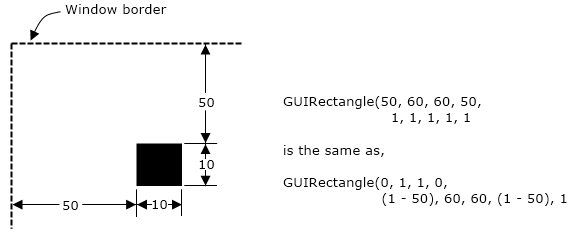
The scaling parameters are also in the order of Left, Bottom, Right and Top. The scale values to apply will always use the formula, (1 - Left), Bottom, Right, (1 - Top).
For example, to position a GUIRectangle using the side scaling parameters:
left = 10;
bottom = 80;
right = 100;
top = 10;
...
GUIRectangle(0, 1, 1, 0 { Unit bounding box },
             1 - (left) { Left scaling },
             bottom     { Bottom },
             right      { Right scaling },
             1 - (top)  { Top scaling },
             1          { No scaling as a whole },
             0, 0       { No movement },
             1, 0, 0, 0, 0 { Visible, not selectable },
             14, 12     { Yellow interior, red outline });
This rectangle will be identical to one drawn using the following constants for the initial bounding box.
GUIRectangle(10, 80, 100, 10 { Unit bounding box },
             1, 1, 1, 1, 1   { No scaling },
             0, 0            { No movement },
             1, 0, 0, 0, 0   { Visible, not selectable },
             14, 12          { Yellow interior, red outline });
As a second example, suppose that you have created the rectangle depicted in the first case above, and that you now want to draw another rectangle, smaller by 3 pixels in all directions, and perfectly centered within the first rectangle
GUIRectangle(0, 1, 1, 0     { Unit bounding box },
             1 - (left + 3) { Left scaling },
             bottom - 3     { Bottom },
             right - 3      { Right scaling },
             1 - (top + 3)  { Top scaling },
             1              { No scaling as a whole },
             0, 0           { No movement },
             1, 0, 0, 0, 0  { Visible, not selectable },
             10, 0          { Green interior, black outline });
Again, substitute the appropriate scaling coordinates into the formula in the positions held by left, bottom, right and top.
