
The allowable range of addresses is dependent upon the device with which you are communicating. For example, a PLC may only have 500 holding registers, and thus it can only address either 40001 through 40501, OR 400001 through 400501 (whichever you prefer), even though the protocol allows for addresses much higher than this.
The following table identifies the value ranges for Modicon outputs, inputs, input registers, and holding registers.
| I/O Type | Type Specified | 5 digit address | 6 digit address |
|---|---|---|---|
| Holding Coil | HC1 - HC65536 | 00001 - 09999 | 000001 - 065535 |
| Input Coil | IC1 - IC65536 | 10001 - 19999 | 100001 - 165535 |
| Input Registers | IR1 - IR65536 | 30001 - 39999 | 300001 - 365535 |
| Holding Registers | HR1 - HR65536 | 40001 - 49999 | 400001 - 465535 |
| Data Logger | DL1:1 - DL16:8 | ||
| Holding Registers Long(1) | HL1 - HL65536 | ||
| Input Registers Long(1) | IL1 - IL65536 |
(1)The Modbus protocol does not include 32-bit addresses, but some devices use these anyway. VTScada supports 32-bit Modbus addresses by way of the text prefixes HL for Holding Long and IL for Input Long. The default data type for 32-bit addresses is SDWord.
when using numeric addressing, the leading digit is significant as it determines the I/O type. Any 4 digit numeric address will be used as a Holding Coil address.
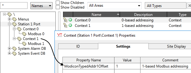
Some applications may be configured using the text prefix addresses that are 0-based, i.e. the first holding coil was at HC0. To permit these applications to work correctly, an application property flag (ModiconTypedAddr1Offset) is used to set the base for text specified addresses.
"Type specified" means addresses such as the HC1 and IR2 format. This does not apply to addresses written as numbers only. (For example, 40001 is always the first address in the 40000 block, and is equivalent to HR1 when ModiconTypedAddr1Offset is 0, or HR0 when ModiconTypedAddr1Offset is 1) If you change the property ModiconTypedAddr1Offset, it will be changed for all Modbus-compatible drivers in the application. If you need some drivers to be zero-based and others to be one based, you can achieve this by creating a parent Context tag for each driver, adding a property named ModiconTypedAddr1Offset to that Context tag. The child driver tag will take the value in the parent Context tag instead of the global property value. (See: Context tag properties, Settings tab)
Bit Addressing
An individual bit in a register (either an Input Register or a Holding Register) may be read or written (for Holding Registers) by appending the address with "/x" where x has a value from 0 to 15 and indicates which bit is to be used. For writes, a read\modify\write cycle is used on the register as the Modicon protocol does not have a bit operation function.
If you are working with long integers, append the text "/sdword" after the bit number. For example: "40050/1/sdword".
Float Addressing
If required, you can use floating point addressing with VTScada. The process will require an adjustment to the way the address is provided to reach the correct register.
Modicon registers are 16 bits wide. In order to get a float address you will need to read 2 sequential registers to get 32 bits. To do this, you will need to know the lowest register address of the pair. Note that this may be odd or even and differs by device.
The address will be formed by entering the lowest address of the pair with the suffix of /FLOAT. e.g. IR9/FLOAT will read the register pair at IR9 and 10, and return the combined value as a float.
Note that driver options determine how the 4 bytes in the combined register pair are ordered to form the float as this will differ by device.
You can read strings from register-based addresses in PLCs such as Delta and Modbus by setting the "String stored in registers" flag of the IO tag, along with specifying the length in bytes. See: I/O Tab, String data type layout
Data Suffixes for Tag I/O Addressing - A list of all available data type suffixes that can be used for tag I/O addresses.
