I/O and Calculations Tag
Counted towards your tag limit if configured to read or write.
Does not count towards your tag limit if configured to calculate without an output address.
This replaces many legacy tags, including: Analog Input, Analog Output, Digital Input, Digital Output, Analog Status, Analog Control, Digital Status, Digital Control, Pump Status, String I/O, Calculation and Function. While those tags will always be supported, you are advised to use the I/O and Calculations tag in their place for all new development work.
The replaced tags are available only in the "All Tag Types" and the "Legacy I/O and Calculations" groups of the Tag Browser.
Within this topic:
I/O Tab Version 1. Analog, Discrete and String
I/O Tab Version 2. 2-bit Digital
Read / Write
If both a read address and a write address are defined and valid, then the read address is used only for feedback and is the only value shown as the value of the tag. If the value at the read address differs from the value written, the tag's Mismatch variable is set to TRUE, as reflected in widgets linked to this tag. The value at the read address is NOT sent to the write address on change.
If there is a write address and no read address, then the value of the tag will reflect the last value that was written. This is true for all data types. Use care however: this does not provide the same information as you would get from having a read address. Without feedback, you know only what the SCADA system attempted to send, not what the state is at the equipment.
If an I/O tag is configured as a Calculation and an output address is provided, each new value calculated will be written to that address. The value will be forced to the data type of the tag. If the data type is numeric, but the expression returns text, nothing will be written. If the data type is discrete, but the expression returns a floating point result, only the integer portion will be written.
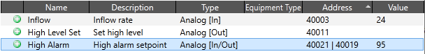
The presence of Read, Write and History addresses are indicated in the Tag Browser by bracketed labels after the type. The order of the labels matches the order of the address. For example, in the following figure, the High Alarm has both a read address (40021) and a write address (40019).
The address of a calculation mode is shown as [Calc] or [Calc/Out]. Memory tags, which have no addresses, are shown as [Mem]
Deadbands for Reading and Logging - Avoid problems with system noise.
If an I/O and Calculation tag does not have a configured address (read, write or history) then it does not count against your tag license. This configuration can be valuable as a "memory tag", which holds a value that is provided by an operator via a widget. The data type can be Analog, Discrete, Digital, or String.
Because memory tags do not write to an address in hardware, it is possible to set their value to Invalid. This can be controlled with the option, "Allow value to be cleared", which is visible in the I/O tab only when no address has been configured. This option also affects certain widgets such as the Droplist Widget, which will show "No Data" (value: Invalid) only if the memory tag can have its value cleared.
2-bit Digital, and all Calculation options of the I/O tag do not count as Memory Tags.
Operators can set the value of a memory tag using any of the standard control widgets. It is also possible to set the values of multiple memory tags in a single operation by using Multi-Write Tags
Memory tag values will persist across application restarts. You can configure a default (initial) value for a memory tag using the input field "Default Memory Value" on the I/O tab, but only if "Allow value to be cleared" is not selected.
Only I/O tags that have an address (read or write) count against your tag license. Memory tags have no address and therefore do not count.
Group Membership
The Historical Data Viewer, Reports Page, and other tools that list tags allow you to sort and filter by "group", where a group may be "analogs", "digitals", "loggers", etc.
Any given I/O and Calculations tag's group membership depends on how you configured it. The rules are:
- Inputs group: The tag has a valid Read or History address, or it is a 2-bit Digital.
- Outputs group: The tag has a valid write address, (2-bit digitals are never in the Outputs group.)
- Loggers group: All I/O and Calculation tags.
- Analogs and Numeric groups: This includes all Analog, Discrete, and their calculation modes.
- Analytics group: This includes all calculation modes.
- Digitals and Numeric groups: This includes all Digital and 2-bit Digital IO tags and their calculation modes.
- Strings group: String and String Calculation mode IO tags
I/O and Calculations tag properties: ID tab
The ID tab of every tag includes the same common elements: Name, Area, Description, and Help ID.
Name:
Uniquely identifies each tag in the application. If the tag is a child of another, the parent names will be displayed in a separate area before the name field.
You may right-click on the tag's name to add or remove a conditional start expression.
Area
The area field is used to group similar tags together. By defining an area, you make it possible to:
- Filter for particular tag groups when searching in the tag browser.
- Link dial-out alarm rosters to Alarm tags having a particular area.
- Limit the number of tags loaded upon startup.
- Filter the alarm display to show only certain areas.
- Filter tag selection by area when building reports.
When working with Parent-Child tag structures, the area property of all child tags will automatically match the configured area of a parent. Naturally, you can change any tag's area as required. In the case of a child tag, the field background will turn yellow to indicate that you have applied an override. (Orange in the case of user-defined types. Refer to Configuration Field Colors).
To use the area field effectively, you might consider setting the same Area for each I/O driver and its related I/O tags to group all the tags representing the equipment processes installed at each I/O device. You might also consider naming the Area property for the physical location of the tag (i.e. a station or name of a landmark near the location of the I/O device). For serial port or Roster tags, you might configure the Area property according to the purpose of each tag, such as System or Communications.
You may define as many areas as you wish and you may leave the area blank for some tags (note that for Modem tags that are to be used with the Alarm Notification System, it is actually required that the area field be left blank).
To define a new area, type the name in the field. It will immediately be added. To use an existing area, use the drop-down list feature. Re-typing an existing area name is not recommended since a typo or misspelling will result in a second area being created.
There is no tool to remove an area name from VTScada since such a tool is unnecessary. An area definition will exist as long as any tag uses it and will stop existing when no tag uses it (following the next re-start).
Description
Tag names tend to be brief. The description field provides a way to give each tag a human-friendly note describing its purpose. While not mandatory, the description is highly recommended.
Tag descriptions are displayed in the tag browser, in the list of tags to be selected for a report and also on-screen when the operator holds the pointer over the tag’s widget. For installations that use the Alarm Notification System, the description will be spoken when identifying the tag that caused the alarm.
The description field will store up to 65,500 characters, but this will exceed the practical limits of what can be displayed on-screen.
This note is relevant only to those with a multilingual user interface:
When editing any textual parameter (description, area, engineering units...) always work in the phrase editor. Any changes made directly to the textual parameter will result in a new phrase being created rather than the existing phrase being changed.
In a unilingual application this makes no difference, but in a multilingual application it is regarded as poor practice.
Help Search Key
Used only by those who have created their own CHM-format context sensitive help files to accompany their application.
Data Type
While the I/O and Calculations tag replaces many types, you must specify how each one is to be used. The data type selection controls the tag's behavior and the configuration options.
Configuration options vary according to the data type that you choose in the ID tab of the properties dialog. In the following notes, you may need to look up or down within a section to find the version that matches the mode you are configuring.
| Data Type | Details | Select when you need to... |
|---|---|---|
| Analog | Analog (Doubles and floating point) |
Read or write values that scale such as temperature or volume. If a deadband is not applied on the logging tab, a default deadband of 0.25% of the scaled range is applied. This value is stored in the application property DefaultAnalogDeadbandFractionOfFullScale |
| Discrete | Analog (Integers) |
Read or write a set of known values, which may scale. |
| Digital | Digital (Binary values, 0 or 1) |
Read or write a value of 1 or 0 from a single address. |
| 2-Bit Digital | Digital (Binary values 00 to 11 (0 to 3)) |
Read a value of 1 or 0 from two address, making this a 4-state digital. Cannot write values to either address. |
| String | Note (Text) |
Read or write a text value. Output padding is handled by widgets rather than the I/O tag. |
Within reason, you can change the data type after creating a tag. If after configuring for one data type, you select another, configuration options that do not apply to the new type are saved but not used. For example, you might initially define the tag as Analog and set scaling parameters. If you change the data type to Digital, the scaling tab is hidden and the scaling parameters are not used, but the values you set will be retained.
Calculation
For any data type, there is a Calculation option. This counts as a separate but matching mode for each listed in the drop-down. (So, Analog -> Analog Calculation)
Use this when you intend to create an expression that will be set the tag's value (or select another tag that this one should mirror). When creating a calculation, the choice of data type affects the values that can be returned by the expression and the set of widgets that can be used to display that value.
- Calculation results can be written to an output address, in which case the tag will count towards your tag license.
- Calculations that do not write to an output address do not count towards your license.
- Any I/O tag with the Calculation mode set does not count as a memory tag. (Memory Tags)
- Calculations do not retain their value across restarts. Use a legacy Analog Status
- In applications that run on multiple workstations, calculations are performed locally on each workstation unless the synchronize option (Sync) is selected. Either mode may be appropriate depending on the purpose of the calculation.
Mode Select when you need to... Analog Calculation
Calculate a numeric value.
Does not read from hardware but may use the value of other tags that do.
Can write to hardware.
Discrete Calculation Calculate a value from a set of known values.
Does not read from hardware but may use the value of other tags that do.
Can write to hardware.
Digital Calculation Calculate a digital value.
Does not read from hardware but may use the value of other tags that do.
Can write to hardware (1, 0, or pulse)
2-Bit Digital Calculation Calculate a 2-Bit digital value. (0 to 3)
Does not read from hardware but may use the value of other tags that do.
Can write to hardware (single address).
String Calculation Calculate a text value.
Does not read from hardware but may use the value of other tags that do.
Can write to hardware.
Some changes of I/O type may harm other work. For example, assume that you have a tag configured as an Analog and drawn using a gauge. If you change the type to String, the gauge will be broken since it cannot display a text value. Note the mode for each data type as given in the preceding table. Changes from one to another data type are likely to cause problems.
Data logged for one data type may not be appropriate for another. Nothing will be lost, but a report for a digital such as "Pump run time" cannot show data logged while the tag was of type String.
HDV plots may need to be reconfigured. If the tag was plotted as a digital, it will not automatically switch to analog.
Work to avoid any need to change the data type of your I/O tags.
Equipment Type
Provides a way to categorize tags that is similar to the Area property but more powerful.
When used with Discrete or Digital I/O types, you can create style for your equipment type that assigns a label and color for each possible value of your tag. This may be especially useful when combined with I/O Multi-Text or the Droplist Widget.
One default type is provided: "Pump". This is used in the Reports page as a filter for the Pump Activity and Pump Discrepancy reports. You can filter based on equipment type in any tag list. Advanced users can create reports or other tools that use Equipment Type as a filter.
You are free to create as many equipment types as you need, and you may do so from within either an I/O tag on the ID tab or a Style Settings tag on the Equipment tab. The instructions are the same in both cases:
- Place the cursor in the Equipment Type field.
(It does not matter whether the field is blank or shows an existing type.)- Type the name of your new equipment type.
- Press the [tab] or [Enter] key on the keyboard.
- Click the Apply button.
The new type is saved.
If the field had shown an existing type before you started, it is not changed.
Equipment type names can be removed the same way that Area properties are removed: First ensure that the name is not in use within any tag, then restart the application.
The Equipment Type of an I/O and Calculations tag is a powerful feature when used with care. Do not assign Equipment Types casually, without a clear plan for how you intend to use this feature.
I/O and Calculations tag properties: I/O tab
The layout for Analog and Discrete modes is described first.
Scroll down for the String and Digital modes.

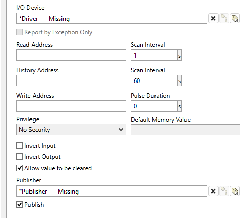
I/O tab for Analog and Discrete modes
I/O Device (Required)
Select the communication driver tag that data will be read from or written to.
By default, the tag will look for a parent tag that is a device driver (*Driver). If none is found, the text "--Missing--" will be displayed. The tag button to the right of the field opens the tag browser, from which you can either select an existing communication driver tag or add a new one. The X button will clear the field. Right-clicking on a tag in the field will open a dialog with which you can add or remove a Snapshot Expression, or open a selected driver's properties dialog.
Report by Exception Only
When selected, the Read Address will not scan (polling will be event-based). The Scan Interval will appear grayed out and set to -1. This setting is only editable when the attached driver supports both Report by Exception and standard polling (such as the DNP3 driver and SNMP driver).
The DNP3 driver and SNMP driver have override settings.
If linked to a driver that only supports Report by Exception, the checkbox will be checked and grayed out.
If linked to a driver that does not support Report by Exception, the checkbox will be unchecked and grayed out.
Read Address (Optional.)
Provide the address within the I/O device from which this tag is to read data. This value must match the configuration of your PLC or RTU hardware. Refer to the Addressing topic for your particular device driver for guidance.
If a Write Address is provided the Read Address is used only as feedback and will set the value of the tag regardless of the value written. If the value in the Read Address does not match the value written then the tag's Mismatch flag is set to true and will be reflected in linked widgets, either as a blink or a mismatch color, according to the widget.
Address Assist: (...)
Several drivers including SNMP, OPC Classic Client, Fisher ROC and others, provide an Address Assist button to help you. The content of the Address Assist dialog will vary according to the driver.
Scan Interval (Read scan interval. Applies only if a Read Address is provided.)
Provide the frequency, measured in seconds, at which the I/O device should be scanned for new data. Reduce system load by setting this as high as possible, as appropriate for the equipment being monitored. If the I/O Device is a Polling driver, which provides its own scan interval, then this field will not accept data. Otherwise, try to keep scan intervals the same, so far as is reasonable, so that drivers can group (coalesce) reads from equipment where you have sequential addresses.
Deadband (On data reading, for Analog values only)
If defined, the value on the device must change by more than this amount before the tag will register it as a new value. A deadband can greatly improve application efficiency by filtering out noise and eliminating unnecessary work to process that noise as if it were useful data.
The deadband is an absolute value, not a percentage, and is specified in terms of the tag's display values if set or the scaled engineering units otherwise. (Refer to notes for the Scaling tab.) If a deadband value is not provided, one will be calculated automatically based on several factors including the logging deadband and the application property, DefaultDriverDeadbandFractionOfFullScale.
See also: Deadbands for Reading and Logging
History Address (Optional. Use only with devices that support this feature.)
If set, then the Read address field becomes optional. This field provides a means of reading values as recorded by a data logger.
If both the read address and the history address are provided, then the read address will be polled for data at the set interval, but the values read from the history address will override the values logged from the read address.
If the identical address is provided for both read and history, then only the read address is used. History values will not be recorded.
The form for the history address will depend on the RTU. Please refer to the addressing reference chapter for your driver.
Typically, history data arrives as an array. If sent to the Read address of an input tag, only the first element is read and the rest discarded. History data must be sent to the History address in order to be fully recorded.
Note that it is not possible to enter a parameter expression directly in the History Address field. As an alternative, you may enter compound address in the Address field using a parameter expression. For example, if Addr, HistAddr and HistoryRate are all properties of a parent tag, the following expression in the Address field will create a compound address with all three components:
concat(.\Addr , "):(" , .\HistAddr , "):(" , .\HistoryRate )
The characters "):(" separate each component of the address. Do not add a leading or trailing parenthesis around the entire expression.
Further information on reading history information can be found in the topic SCADAPack History Read
For numeric values (not String), a deadband is applied automatically to the values read on the History Address. The calculation uses the application property, DefaultAnalogDeadbandFractionOfFullScale.
CalculatedHistDeadband = PickValid(Threshold, (HighScaleValue - LowScaleValue) * \DefaultAnalogDeadbandFractionOfFullScale, 0);
Scan Interval (History scan interval. Applies only if a History Address is provided.)
Sets the time between polls of the history data logger. If a History address has been set, but this field is left blank, then it will default to the value set in the Scan Rate field. The recommended value for this field is 60 seconds. Lesser values may cause communications to slow down.
Write Address (Optional. Do not configure for tags that are input-only.)
Provide the address within the I/O device to which this tag is to write data. This value must match the configuration of your PLC or RTU hardware. Refer to the Addressing topic for your particular device driver for guidance.
For some drivers (SNMP and the OPC Classic Client) an address browser is provided to assist you.
Privilege (Applies only if a Write Address is provided)
Limit the ability to write using this tag to only those operators who have been granted the selected custom privilege. See: Restrict Access to Output Tags
Publisher
Select a Publisher tag if one is required for your configuration. Defaults to [*Publisher]. Eligible tags (Publisher tags that are a direct ancestor, uncle or sibling) will automatically link or you can select a tag manually. VTScada publishing configurations may include:
- An OPC client when your application has a properly-configured OPC Classic Server Setup tag.
- A Sparkplug B Edge Node or a Sparkplug B Edge Device.
- A MultiSpeak interface if properly configure. See: MultiSpeak Support.
- A Data Diode publisher or client tag.
Publish
This tag will publish data if a publisher is configured and this setting is enabled. If this setting is disabled, the tag will stop publishing data.
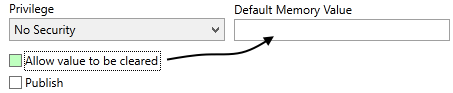
Allow value to be cleared
Enabled only for memory tags (I/O tags with no read or write address). When selected, widgets such as the Droplist Widget can show No Data (value: Invalid) as a option.
Default Memory Value
Can be used to set a default value when this tag is configured as a Memory tag (Memory Tags). This option cannot be used when Allow value to be cleared is selected.
I/O Tab, String data type layout
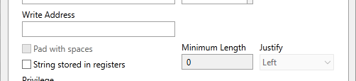
Variation for Strings, showing options for output padding and storage in registers
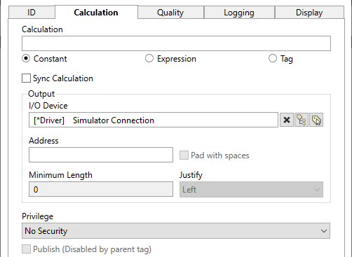
Pad with spaces
Enabled only after a Write Address has been entered. If selected, you will have the option of specifying a minimum length for output strings. Values shorter than this will be padded with spaces according to the selected Justify option.
String stored in registers
Select this option if reading a string from a series of numeric registers in PLCs such as Modbus or Delta, where the characters are encoded in the register values. This option requires the length of the string to be set so the tag can know how many registers to read or write.
Minimum Length
Enabled only after "Pad with spaces" or "String stored in registers" is selected.
- When used for Pad with spaces, this sets the minimum length for output strings.
- When used for String stored in registers, this sets the size of the string in bytes to ensure the proper number of registers are read to read the string.
Justify
Controls whether spaces are added to the left, the right or both sides of output text in order to achieve the required minimum length.
Reading Strings
If reading string data, note that not all PLCs will store characters in the same in order in registers. Further, registers may vary in size from one PLC type to another.
If the string read from your registers has characters that are not in the order you expected, use the BuffOrder() function in an expression to swap the order of the characters so that they do match what is expected. Do this by creating one I/O and Calculations tag to read the value, then create a second with an expression to read the value in the first and apply the BuffOrder function. The second I/O and Calculations tag will not count against your license because it does not use a read or write address.
Better practice is to program the PLC to send an integer code that can be mapped to a phrase in VTScada. The result can be used in a multilingual application and can reduce the amount of data transmitted.
Example: A BuffOrder call for a word-sized register with the character order swapped:
BuffOrder([<SourceTag>], 0, 1, 2, N)
...where the value N should be the half the length of the buffer.
I/O tab for the Digital data type
Variations in this mode are as follows:
- No Deadband values
- Addition of the Invert Input and Invert Output
- Addition of a pulsed output option
Pulse Duration
The pulse duration can be no less than 0 and no greater than 86400 (one day)
When set to a positive, non-zero number, the tag will a specified signal (1 or 0) to the Write Address, then retain that value for the number of seconds specified by the duration. At the end of that time, the opposite value is sent to the write address and the tag's value returns to its normal state.
For example, if a linked button widget is configured to write a 1, this tag will write the value 1 when the button is pressed and will hold the value 1 for the specified duration. At the end of the duration, a 0 is written and the tag's value returns to 0. Writing a zero using a second button linked to the same tag has no effect, except in the case that a pulse is in progress, in which case it will cancel the pulse.
If Invert Output is selected, then this tag's base state is 1 and it can be used to write a 0 (zero).
Triggering a pulse repeatedly will reset the timer with each press of the button. This allows a long pulse to be sent, but the pulse following the last button press will be no longer than the set duration.
Invert Input
If the Invert Input check box is selected, the value of the tag being used as the data source is reversed (i.e. a 1 becomes a 0 or a 0 becomes a 1).
Invert Output
If selected, the value being written is reversed (i.e. a 1 becomes a 0 or a 0 becomes a 1).
If the read address is the same as the write address, or the read address is blank and the history address is the same as the write address, then the Invert Output field will be disabled and the value will be set to the same value as Invert Input, preventing a mismatch.
I/O and Calculations tag properties: ID tab version 2
Used for: 2-bit Digital
2-bit Digitals can only read. Do not use for tags that must write. There is no option to read from a History address with a 2-bit Digital.
The reported value is the data at the Bit 0 address plus two times the data at the Bit 1. If the Bit 0 Address field does not contain a valid address, this tag will not read.
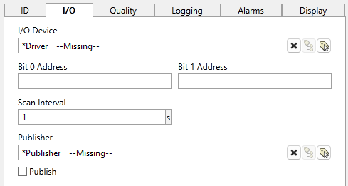
I/O tab, only for 2-bit Digitals
I/O Device (Required.)
Select the communication driver tag from which data will be read.
By default, the tag will look for an ancestor or sibling tag that is a device driver (*Driver). If none is found, the text "--Missing--" will be displayed. If more than one equally qualified tags are found, "--Error: Multiple Drivers--" will be displayed. The tag button to the right of the field opens the tag browser, from which you can either select an existing communication driver tag or add a new one. The X button will clear the field. Right-clicking on a tag in the field will open a dialog with which you can add or remove a Snapshot Expression or open a selected driver's properties dialog.
Bit 0 Address (Required.)
The Bit 0 Address property is the address of the low order bit for this tag in the I/O device.
Bit 1 Address (Required.)
The Bit 1 Address property is the address of the high order bit for the digital input in the I/O device.
Address Assist
Several drivers including SNMP, OPC Classic Client, Fisher ROC and others, provide an Address Assist button to help you. The content of the dialog will vary according to the driver. Within this guide, refer to the Driver Addressing topic for your driver for more information.
Scan Interval (Required.)
Provide the frequency, measured in seconds, at which the I/O device should be scanned for new data. Reduce system load by setting this as high as possible, as appropriate for the equipment being monitored. If the I/O Device is a Polling driver, which provides its own scan interval, then this field will not accept data. Otherwise, try to keep scan intervals the same, so far as is reasonable, so that drivers can group (coalesce) reads from equipment where you have sequential addresses.
Publisher
Select a Publisher tag if one is required for your configuration. Defaults to [*Publisher]. Eligible tags (Publisher tags that are a direct ancestor, uncle or sibling) will automatically link or you can select a tag manually. VTScada publishing configurations may include:
- An OPC client when your application has a properly-configured OPC Classic Server Setup tag.
- A Sparkplug B Edge Node or a Sparkplug B Edge Device.
- A MultiSpeak interface if properly configure. See: MultiSpeak Support.
- A Data Diode publisher or client tag.
Publish
This tag will publish data if a publisher is configured and this setting is enabled. If this setting is disabled, the tag will stop publishing data.
I/O and Calculations tag: Calculation tab
Used for: All Calculation modes
There are three versions of this tab, depending on the data type of the tag. Select the one you are interested in from the following drop-downs.
It is important that the calculation expression match the data type. For example, a digital calculation expression should have a value of 0 or 1. Proper behavior cannot be guaranteed unless the result matches the tag's data type. For example, a text expression for a discrete data type will resolve to an Invalid.
If the Sync Calculation option is not selected, Calculations are performed locally on each machine running the application and are not synchronized between machines.
To protect your system, changes in numeric calculations are subject to the built-in deadband, DefaultCalculationDeadbandFractionOfFullScale
Note that Value is a binary choice when set to Constant. Select Expression to open the usual expression field and editor button.
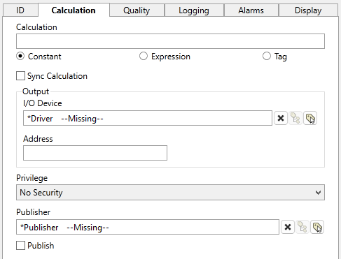
Calculation
Holds the expression that this tag should calculate. (Expressions) While you can specify a constant or select another tag to mirror it's value, in most cases you will select the Expression option, then click on the  button in order to open the expression editor.
In calculation mode, the I/O tag does not retain its value across application restarts. If this is required, use the legacy Analog Control Tags.
Sync Calculation
The default is for calculations to be done on each local machine. If Sync Calculation is selected, the calculation is performed only on the current server and the value broadcast to other machines.
"Current server" means the server for the I/O tag's driver, if there is one. This can be set manually by 'I/O Device' (seen below), and defaults to the next relevant ancestor or sibling tag through automatic linking (see 'Relative Paths - Tag Relationships' for linking behaviors). If no valid driver is specified for the I/O tag, calculations use the Network Values server as the "current server."
This process is resource intensive. VTScada uses RPC (Remote Procedure Call) to distribute processing labor amongst networked machines. One recalculation will cause all machines to update and frequent updates will rapidly increase their collective disk activity. Enabling Sync Calculation should be reserved for situations where otherwise the client is unable to independently calculate the same result as the server .
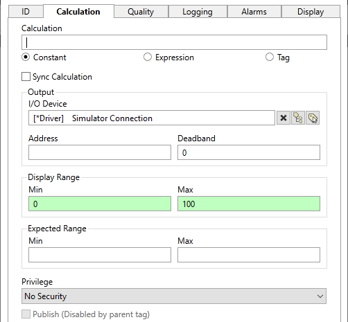
I/O Device (Optional)
Select the communication driver tag that data will be read from or written to.
By default, the tag will look for a relevant ancestor or sibling tag to serve as device driver ("[*Driver]"). If none is found, the text "--Missing--" will be displayed. The tag button to the right of the field opens the tag browser, from which you can either select an existing communication driver tag or add a new one. The X button will clear the field. Right-clicking on a tag in the field will open a dialog with which you can add or remove a Snapshot Expression, or open a selected driver's properties dialog.
Address (Optional)
Provide the address within the I/O device to which this tag is to write data. This value must match the configuration of your PLC or RTU hardware. Refer to the Addressing topic for your particular device driver for guidance.
For some drivers (SNMP and the OPC Classic Client) an address browser is provided to assist you.
Deadband (Numeric and Discrete Calculation only. Optional.)
Changes in value smaller than this are not written by the tag.
Expected Range - Min and Max (Numeric and Discrete Calculation only. Optional.)
Used to provide default minimum and maximum values to certain widgets. (The Numeric Calculation type does not have a scaling tab, where these values would otherwise be set.)
By definition, an expected range should not overlap an alarm setpoint. If you do configure an overlap, do not expect both to show in any widget.
Pulse Duration (Digital Calculation only. Optional)
When set to a positive, non-zero number, the tag will send a specified signal (1 or 0) to the Write Address, then retain that value for the number of seconds specified by the duration. At the end of that time, the opposite value is sent to the write address and the tag's value returns to its normal state.
An important distinction from the Digital data type is that the calculation tag’s value does not return to its original state once the pulse its done (just the written value). To reset the pulse for a digital calculation, the expression’s value must go to 0 and then back to 1. This means that triggering a pulse repeatedly does not create a single long pulse, as in the normal digital case.
Invert Output (Digital Calculation only. Optional)
If selected, the a calculated state of the tag of 1 write as 0.
Privilege (Applies only if a Write Address is provided)
Limit the ability to write using this tag to only those operators who have been granted the selected custom privilege. See: Restrict Access to Output Tags
Publisher
Select a Publisher tag if one is required for your configuration. Defaults to [*Publisher]. Eligible tags (Publisher tags that are a direct ancestor, uncle or sibling) will automatically link or you can select a tag manually. VTScada publishing configurations may include:
- An OPC client when your application has a properly-configured OPC Classic Server Setup tag.
- A Sparkplug B Edge Node or a Sparkplug B Edge Device.
- A MultiSpeak interface if properly configure. See: MultiSpeak Support.
- A Data Diode publisher or client tag.
Publish
This tag will publish data if a publisher is configured and this setting is enabled. If this setting is disabled, the tag will stop publishing data.
I/O and Calculations tag: Scaling tab
Used for: Analog and Discrete
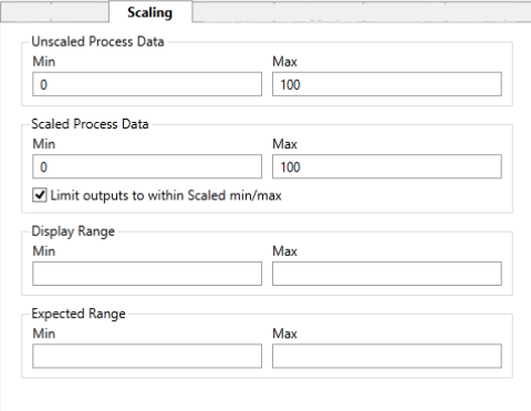
Only the first four fields affect the value.

|
VTScada assumes a linear relationship between the values as shown. The scaled and unscaled process values you provide set the slope of the line, allowing any value on one axis to be mapped to the other. The values do not limit what the tag can read, but the Scaled Process Min and Max values do limit what the tag can write. |
Min and Max Unscaled Process Data (Required.)
Use these to tell VTScada the range of raw values to expect from or write to hardware.
Min and Max Scaled Process Data (Required.)
These values must match the Unscaled Min and Max values. VTScada uses them to convert between the engineering units shown in the SCADA system and the raw values read from or written to the hardware. By default, the "Limit outputs to within Scaled min/max" option is selected. If you deselect this option, the output range limit is disabled. This allows any value, including negative integers, to be sent to the tag. However, scaling is still applied to the new output value, regardless of the value sent to the tag.
The Min and Max values should not be the same value for both of these fields. If they are, the tag will return an invalid value.
Display Range Min and Max (Optional.)
These two fields have no effect on the value of the tag.
Set the Min and Max Display Range values to define the default scale range for the HDV trend view and certain widgets, such as the various meters. Use these when values are expected to stay within a portion of the full scale range and it is therefore helpful to adjust the displayed range as needed.
If left blank, the Scaled Process Data Min and Max values will be used as the Display Range values.
Expected Range Min and Max (Optional.)
These two fields have no effect on the value of the tag.
Used to provide default minimum and maximum values to certain high performance graphics widgets. If left blank, the expected range feature of those widgets is not drawn. Both must be provided.
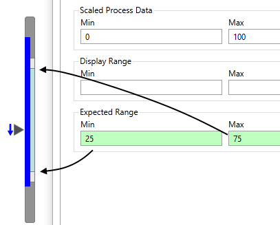
The expected range is shown in pale blue.
The color is controlled by the assigned Style Settings tag.
I/O and Calculations tag: Quality tab
Used for: All types
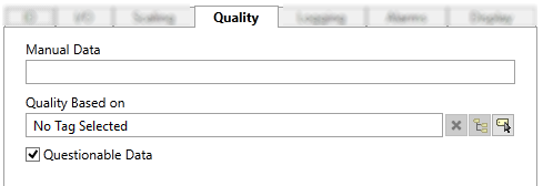
Quality tab for all types.
Manual Data
Sets a constant value that will be used instead of live data. Use when testing a new tag if you need to check behavior when a value is outside the normal operating range. Tags that have manual data are marked by a flashing exclamation mark within any linked widgets. Logged values are marked with an exclamation. Always reset this to blank after testing.
If the tag is configured with an output address, and (in the case where this tag is protected by a user-defined security privilege) if the person configuring the Manual Data value has required privilege, then the manual data value will be written to the defined output address.
In the case where the I/O tag was configured as a Calculation, the manual data value will override any expression value .
The Quality Based On field can be tied to a driver tag, a tag that monitors driver communication errors, a register in the PLC or RTU, or any other indication of system health. The tag you are configuring will use that value to set an internal variable named QualityIssue. You may test this value in an expression: [TagName]\QualityIssue.
QualityIssue will be a 0 or 1 where "Good Quality" is defined as a value of "0 or Invalid" and "Bad Quality" is defined as any valid, non-zero value. This is consistent with driver communication error values.
Widgets that use the System Style tag will display bad quality using the color set on the Exceptions tab.
Questionable Data
Use the Questionable Data parameter to flag this tag’s data in the event that you suspect the values it is reporting might not be accurate, or when this tag has initially been created and you wish to ensure that its data is marked for extra monitoring.
I/O and Calculations tag: Logging tab
Used for: All types
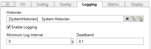
Logging tab for all types
Historian
If an Historian tag is selected, this tag's run-time values will be saved for use in reports and the Historical Data Viewer. Historian configuration and advanced logging options are described in the discussion of the Historian Tags.
If your goal is to disable logging, set the Enable parameter (below) to 0 rather than deleting the Historian parameter.
There are consequences if you change the selected Historian tag after you have begun collecting data. If you switch to a new Historian (perhaps for organizational or load sharing purposes), the data collected for this tag by the previous Historian will become inaccessible. Historian selection and configuration should be done during the project design stage.
Enable Logging
If values should be logged only while certain conditions are true, you can tie the Enable Logging option to any tag or expression that will change from zero (logging disabled) to 1 (logging enabled). Do so by right-clicking on the Enable Logging check box and creating a parameter expression. The "Optimize..." option in the expression should be deselected. For detailed instructions (and important warnings) see: Automated Tag Configuration.
Minimum Log Interval
Here, "Interval" refers to time measured in seconds. If set to a valid number greater than zero, and if the tag has a valid value, that value will be recorded to the history every interval, regardless of whether it has changed from the last write.
In most cases, this should be left blank, allowing values to be written on change larger than the specified deadband.
As of release 12.1.42, logging of I/O tags has changed as follows: Values will be logged on interval OR on change but not both. If both are needed, create a second (free) I/O tag using an expression that watches the value of the first tag. Log the first on interval and the second on change. Attempting to do both on the same tag introduces a small but important risk of values being recorded out of sequence if the remote device is sending timestamped data and its clock is not synchronized with the server.
Deadband (Analog, Discrete, and matching calculation modes only)
Every change in value will be written to the Historian. You are advised to set a deadband so that you do not fill the log with small changes that amount to system noise. (See: Deadbands for Reading and Logging)
When using the Analog data type, a default deadband of 0.25% of the display range if set and the scaled range otherwise. This value is stored in the application property DefaultAnalogDeadbandFractionOfFullScale
I/O and Calculations tag: Alarms tab (Basic analog type)
Used for: Analog, Discrete, and matching calculation modes
The basic version of this tab allows quick configuration of up to four alarms, two high-level and two low-level. Unlike the legacy Analog Status tag, you do not need to enable the alarm in addition to selecting a priority.
Do not configure an alarm for tags that write but do not read.
Tag parameter expressions have "Optimize to only evaluate at tag initialization" selected by default.
Do not deselect this option for alarm parameter expressions. Do not use non-optimized expressions for alarm parameters.
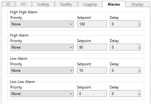
Basic mode of the Alarms tab for analog values. The Discrete mode includes the option of a State Alarm.
Priority
Use the drop-down tool to select the priority for each alarm that will be triggered by this tag. The available priorities are:
- None
- 0 - Event
- 1 - Critical Alarm
- 2 - High Alarm
- 3 - Warning Alarm
- 4 - Notice Alarm
If you have defined your own Alarm Priority Tags, those will also be available for selection.
Setpoint
Sample setpoints are provided, based on the default scale values of the tag. You must change these to the setpoints at which an alarm should be triggered. To link the setpoint to another tag or an expression, use the Advanced version of this tab.
Delay
To avoid nuisance alarms due to transient spikes in value, set a delay in seconds. The tag's value must reach or pass the setpoint for this length of time before an alarm occurs. To set a deadband on the value, use the Advanced version of this tab.
State (Discrete)
The state for which the alarm will occur.
I/O and Calculations tag: Alarms tab (Advanced type)
Content varies. Used for: Analog, Discrete, Digital, 2-bit Digital, and matching calculation modes
For all the following descriptions, assume that for each data type, the matching calculation mode also applies. For example, what applies to Analog also applies to Analog Calculation.
For Analog and Discrete, after switching to the advanced tab and making a configuration change, there is no option to switch back to the basic tab. If you use the advanced mode to do any alarm configuration, the basic option will no longer be available. If you close the properties dialog without doing advanced alarm configuration, then the basic tab will still be available the next time you open the dialog.
Tag parameter expressions have "Optimize to only evaluate at tag initialization" selected by default.
Do not deselect this option for alarm parameter expressions. Do not use non-optimized expressions for alarm parameters.
The following figure is a composite of all possible parameters.
No single version of the advanced Alarms tab includes all the parameters shown here.
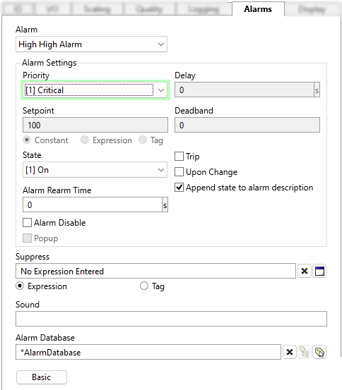
A composite of all alarm parameters.
>> No single version includes all the parameters shown here <<.
Alarm (Analog, Discrete)
Select any of the four built-in alarms that are available for Analog and five for Discrete I/O types.
A Discrete I/O tag can be configured with high or low alarms like an Analog, or with a state alarm like a Digital.
Alarm (Digital, 2-bit Digital)
The only available choice is "State", meaning that alarms are triggered by a change to a defined state value.
String I/O types do not have built-in alarms.
Priority (All types)
Use the drop-down tool to select the priority for the selected alarm. This will also enable the alarm.
Delay (All types)
To avoid nuisance alarms due to transient spikes in value, set a delay in seconds. The tag's value must reach or pass the setpoint for this length of time before an alarm occurs.
Setpoint (Analog and Discrete)
The value at which the alarm will occur. An expression or tag can be used to create a variable setpoint for Analog or Discrete data types.
State (Digital and Discrete)
The state for which the alarm will occur. For Digitals, the triggering state may be [0] OFF, [1] ON, or [Upon Change].
For Discrete tags, it may be any value or Upon Change.
State (2-bit Digital)
The state for which the alarm will occur.
Options include [0] OFF, [1] ON, [2], [3] or [Upon Change]
Trip Alarm (Digital, 2-bit Digital, Discrete)
Select if this alarm is to be a trip alarm. When triggered, a trip alarm is not affected by the changing status of the equipment.
For comparison, a "level alarm" has an active state (the level is at or beyond the trip point) and a normal state (the level has returned to normal operating conditions.) A trip alarm simply trips and does not monitor whether the cause returns to normal operating conditions.
After being tripped, all visible and audible notifications will continue until an operator acknowledges the alarm.
Append State to Alarm Description (Digital, 2-bit Digital, Discrete)
When selected, the description found in the Alarm List will be appended with the state of the tag. This status will update for Alarm, Normal and Trip events.
Deadband (Analog and Discrete)
Does not change the setpoint. Use this to avoid nuisance alarms that activate and normalize due to a value that fluctuates into and out of the alarm condition as defined by the type and setpoint. The level must drop (or high alarms) or rise (for low alarms) by this much past the setpoint before the alarm condition is considered to have normalized.
Alarm Rearm Time (All types)
Measured in seconds. If a valid, non-zero value is given then if the alarm has been acknowledged, but remains active for the time shown in this field, the alarm will return to the unacknowledged state. Audible and visible warnings configured for this alarm’s priority level, will again be displayed.
Does not apply if Trip is selected. (Digital types only)
Alarm Disable (All types)
Select to flag the alarm as disabled without changing other configuration. Disabling of alarms is typically used in situations where you wish to avoid false alarms. For example, in the event that routine maintenance is being performed on the equipment represented by this tag, or when you are aware that another interruption in communications will occur for a period of time. In such situations, the alarm can be disabled until the maintenance is complete and communications are reestablished.
Many sites like to tie this property to Digital tag so that many alarms can be disabled at the same time for maintenance. That option is not available with the built-in alarms, but you could use Alarm Tag instead.
Disable or Enable AlarmsDisable or Enable Alarms
Suppress
Create an expression or select a tag that will suppress the alarm when TRUE and unsuppress it when FALSE.
In an I/O tag, there is only one Suppress parameter, and all configured alarms are suppressed or enabled with it. If you need to suppress some alarms that are triggered by an I/O tag but not others, consider using Alarm tags rather than built-in alarms.
Popup (All types)
The application property AlarmPopupsEnable must be set to 1 (Alarms Tab of the Edit Properties Page). If set, a pop-up dialog will be displayed whenever the respective alarm is triggered. This feature should be used sparingly.
Sound (All types)
The Sound field can be set to blank, 0, 1, or to the name of a .WAV sound file to be played.
- If 0, no sound will be played when this alarm is triggered.
- If blank or 1, an alarm sound whose properties are configured on the associated Alarm Priority tag will be played.
- If the name of a .WAV sound file, it will override any alarm sound configured for the associated Alarm Priority tag. If the specified sound file is not found, the alarm will revert to using tones as specified in the associated Alarm Priority tag.
The .WAV file must be stored in the application folder and must be added to the application by using the Import File Changes Tool
Alarm Database
This tag will be auto linked to the closest ancestor or else sibling Alarm Database tag and the hierarchy. If none found, it will use the System Alarm Database.
Use this parameter to link the tag to an alternate Alarm Database of your choice.

Every tag has public variables that advanced developers can use in expressions or when working in the Idea Studio. Those properties are described here for the sake of providing full information.
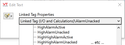
Of particular note are the following variables that can be used to monitor the alarm status of an I/O tag.
| HighHighAlarmActive | |
| HighHighAlarmUnacked | |
| LowLowAlarmActive | |
| AlarmActive (state alarms) | AlarmUnacked |
Further information about how to refer to tag properties with expressions can be found in the topic, Automated Tag Configuration.
I/O and Calculations tag: Display tab
Layout and content varies by type
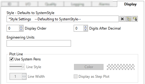
Display properties for analog data types including calculations.
Other data types will have fewer properties.
Style
When this tag is represented on screen by widgets that can use a Style Settings tag, you can save development time by choosing the Style Settings tag that holds the correct display configuration for this tag instance. (See: Style Settings Tags)
The default configuration will search for the first ancestor or then sibling tag of the Style Settings type. If there is none, it will use System Style, which is the default style tag that is automatically part of every new VTScada application.
Display Order
Common to all type selections. Used to specify the placement of this tag when viewed in a Site Details Page.
Digits After Decimal
Analog and Numeric Calculation. Limits the number of digits displayed after the decimal point wherever this tag is displayed, including the Historical Data Viewer. May be overridden in certain widgets. (See: Deadbands for Reading and Logging)
Engineering Units ((Analog, Discrete, and matching calculation modes)
Provide the units of measure that the scaled value represents. This text will be used by widgets that include engineering units as part of the display. Possible values for this field include "rpm", "degrees C", "%", etc.
You can add a degree symbol to the engineering units by holding down the Alt-key while typing 0176 on the numeric keypad. Release the Alt-key before typing the C or F.
Plot Line
Options in this section control how this tag's pen is shown in the Historical Data Viewer (HDV) and widgets that support I/O tag features such as Sparklines.
Use System Pens
If selected (default) no pen configuration from this tag is made available to the HDV. Widgets that can take display characteristics from the linked I/O tag will have that option disabled.
Deselecting this option does not force the HDV or linked widgets to use display settings from this tag.
Default values are assigned for the following:Line Style
Analog, Discrete, Digital, 2-bit Digital, Numeric Calculation. Default appearance of the line when plotted in any version of the Historical Data Viewer. Defaults to a continuous line. May be overridden in any plot. Options include a variety of dash and dot combinations.
Line Width
Analog, Discrete, Digital, 2-bit Digital, Numeric Calculation. Default width of the line when plotted in any version of the Historical Data Viewer. Defaults to a single pixel. May be overridden in any plot, up to 9 pixels.
Color
Select the color to use when representing this tag in the HDV.
Display as Step Plot
Intended for Discrete data types. The lines drawn between data points will not be sloped. Changes in values will be practically vertical and plateaus will be horizontal. Like steps.
I/O and Calculations tag Widgets
All widgets that could be used for a numeric, digital or string value are available, but some may not be appropriate for a given configuration. It is up to you to select widgets that will work with a given I/O and Calculations tag. See: Widget Reference
I/O Multi-Text - Display predefined labels for matching discrete values
