Not counted towards your tag license limit.
The Bristol Network tag provides a common network interface to one or more Bristol Driver tags. This tag defines the interface to the network of RTUs connected to a single port in VTScada and is configured differently for BSAP networks vs. IBP networks.
For BSAP networks, a single serial (or TCP) port in VTScada is used to communicate with one or more RTUs directly connected to that serial port (the level 1 devices) which in turn can communicate with a number of RTUs connected to their serial ports, up to 6 levels deep. For these configurations, a single VTScada Bristol Network tag is used for the entire BSAP network.
For IBP networks, each individual RTU that is connected to VTScada (each Ethernet connected RTU) will require its own unique Bristol Network tag. For a setup of 20 RTUs connected directly to an Ethernet work, you will require 20 Bristol Network tags and 20 Bristol Driver tags. If you need to communicate with RTUs connected to the serial ports of the Ethernet (IBP) connected RTUs, then you can do this through the Bristol Network tag that is used to connect to the RTU on the Ethernet (using an IBP configured tag) , and from there to the serially connected RTUs. See configuration examples provided in Bristol BSAP/IBP Driver.
Note that in the context of the VTScada Bristol Network & Bristol Driver tags, "directly connected on Ethernet" means connected to the Ethernet port on the RTU. If communicating to a serial port on an RTU using an Ethernet to serial converter, then this is a BSAP network, not an IBP network
Use in Ethernet Connected Devices
In order for VTScada to be able to set the NRT and clock of an Ethernet connected RTU, the IP address of the VTScada server must be defined as one of the RTU’s NHP servers using the Bristol "Flash Configuration" utility in the LocalView or NetView programs.
Bristol BSAP/IBP Driver - Includes examples of network configuration.
The ID tab of every tag includes the same common elements: Name, Area, Description, and Help ID.
Name:
Uniquely identifies each tag in the application. If the tag is a child of another, the parent names will be displayed in a separate area before the name field.
You may right-click on the tag's name to add or remove a conditional start expression.
Area
The area field is used to group similar tags together. By defining an area, you make it possible to:
- Filter for particular tag groups when searching in the tag browser.
- Link dial-out alarm rosters to Alarm tags having a particular area.
- Limit the number of tags loaded upon startup.
- Filter the alarm display to show only certain areas.
- Filter tag selection by area when building reports.
When working with Parent-Child tag structures, the area property of all child tags will automatically match the configured area of a parent. Naturally, you can change any tag's area as required. In the case of a child tag, the field background will turn yellow to indicate that you have applied an override. (Orange in the case of user-defined types. Refer to Configuration Field Colors).
To use the area field effectively, you might consider setting the same Area for each I/O driver and its related I/O tags to group all the tags representing the equipment processes installed at each I/O device. You might also consider naming the Area property for the physical location of the tag (i.e. a station or name of a landmark near the location of the I/O device). For serial port or Roster tags, you might configure the Area property according to the purpose of each tag, such as System or Communications.
You may define as many areas as you wish and you may leave the area blank for some tags (note that for Modem tags that are to be used with the Alarm Notification System, it is actually required that the area field be left blank).
To define a new area, type the name in the field. It will immediately be added. To use an existing area, use the drop-down list feature. Re-typing an existing area name is not recommended since a typo or misspelling will result in a second area being created.
There is no tool to remove an area name from VTScada since such a tool is unnecessary. An area definition will exist as long as any tag uses it and will stop existing when no tag uses it (following the next re-start).
Description
Tag names tend to be brief. The description field provides a way to give each tag a human-friendly note describing its purpose. While not mandatory, the description is highly recommended.
Tag descriptions are displayed in the tag browser, in the list of tags to be selected for a report and also on-screen when the operator holds the pointer over the tag’s widget. For installations that use the Alarm Notification System, the description will be spoken when identifying the tag that caused the alarm.
The description field will store up to 65,500 characters, but this will exceed the practical limits of what can be displayed on-screen.
This note is relevant only to those with a multilingual user interface:
When editing any textual parameter (description, area, engineering units...) always work in the phrase editor. Any changes made directly to the textual parameter will result in a new phrase being created rather than the existing phrase being changed.
In a unilingual application this makes no difference, but in a multilingual application it is regarded as poor practice.
Help Search Key
Used only by those who have created their own CHM-format context sensitive help files to accompany their application.
Server List
Select (or create) a named server list.
Bristol Network properties Communication tab
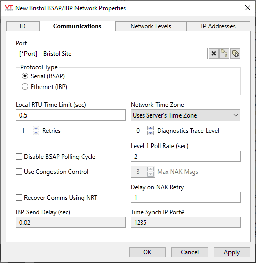
Port
Communications port tag that the driver will use. For BSAP (Serial) protocol, this is typically a Serial Port tag but may also be a TCP/IP Port tag or a UDP/IP Port tag if connecting to a serial RTU via an Ethernet to Serial converter.
For IPB protocol, this must always be a UDP/IP port tag with both its Remote Port Number and Local Port Number fields set to 1234.
Use in Ethernet Connected Devices: In order for VTScada to be able to set the NRT and clock of an Ethernet connected RTU, the IP address of the VTScada server must be defined as one of the RTU’s NHP servers using the Bristol "Flash Configuration" utility in the LocalView or NetView programs.
Protocol Type
Selects the type of communication that the drivers will use on this network. For direct connections to RTUs using serial, select the "Serial (BSAP)" option, for connection to RTUs via an Ethernet port on an RTU, select the "Ethernet (IBP)" option.
Note that the protocol Type selection sets the format of the data sent to and received from the RTUs on the network and does not necessarily match the VTScada port type used. To determine which protocol to use, the following guide may be helpful:
- If communicating directly from VTScada to the Level 1 RTUs on the communication network via a serial port on the RTU, use the Serial (BSAP) protocol
- If communicating directly from VTScada to the Level 1 RTUs on the communication network via an Ethernet to serial converter and then to a serial port on the RTU, use the Serial (BSAP) protocol even though it is being transported via Ethernet TCP/IP.
- If communicating directly from VTScada to the Level 1 RTUs on the network via an Ethernet port on the RTU, use the Ethernet (IBP) protocol.
Local RTU Time Limit
Sets the local timeout in seconds for a directly connected RTU to respond. Note that on multi-level networks, this timeout only applies to the level 1 devices. For RTUs at different network levels, different time limits can be applied.
Retries
Set the number of times to retry a message before declaring it failed. Defaults to 1.
Disable BSAP Polling Cycle
For BSAP networks only, this option disables the background BSAP polling cycle and can be used to reduce communication link traffic in a limited number of system configurations. Select this option only if your configurations meets ALL of the following criteria:
- Using BSAP serial protocol
- All devices are connected as Level 1 devices (no store and forward in use)
- All Devices support "Immediate Response" messages – this is typically only newer ControlWave hardware
- VTScada is not polling or processing alarms from devices
- RBE is not used
Use Congestion Control
For BSAP networks only, this option prevents sending new messages to a local BSAP node if it reports multiple NAK responses. When this situation is detected, any new messages are put in a "Wait" state and will be sent only after the node responds with a non-NAK response. If the node does not respond with a non-NAK after 2 poll cycle times for the corresponding network, the message is dropped and an error raised in the driver.
Recover Comms Using NRT
For BSAP networks only, this option selects whether VTScada will send NRT (Network Routing Table) and Time Synchronization commands to a node that it detects is not responding. This is the Bristol-recommended means to recover dead nodes but can result in unnecessary network traffic if enabled. If not enabled, a standard poll message is sent to dead nodes to recover communication.
IBP Send Delay
When using IBP protocol, the VTScada Bristol Network tag can batch up several commands into a single UDP/IP packet for transmission to the RTU. This setting defines the time that the driver will wait after receiving a single command before sending to the RTU. If one or more commands are ready to send within the time limit, they will be added to the original packet destined for the RTU. If the time expires and no more commands are ready to send, then the packet is sent to the RTU. Increasing this time reduces the number of packets sent but can slow the communication down due to extra delays.
Network Time Zone
The time zone for all RTUs connected to a network tag. This is a global setting for a given Bristol Network and is used to both set the time in the RTUs when requested, and to properly decode the time-stamped data read from the RTUs.
Diagnostics Trace Level
Used to set the level of the diagnostics sent to a trace file hat is output to the application’s Data\TraceFiles directory. When set to 0, the diagnostics file output is not written. Values of 1 through 3 set the tracing level, with 3 being the most verbose. Note that this feature can impact system performance, particularly at level 3, and should be used only when network issues need to be diagnosed.
Level 1 Poll Rate (sec)
For BSAP networks only, the rate (in seconds) at which to poll the level 1 nodes. The VTScada Bristol driver follows the rules set out in the Bristol documentation for BSAP polling, refer to these documents for selecting an appropriate poll rate.
Max NAK Msgs
Maximum number of NAK responses before a node is placed in the Wait state
Delay on NAK Retry
The delay before retrying a NAK'd message (in seconds).
Time Sync IP Port #
On Ethernet connected RTUs (IBP), this setting is the UDP/IP port number on which the RTU will request time synchronization. The port number will normally be set to the default of 1235 unless it is changed in the configuration of the RTU.
Bristol Network properties Network Levels tab
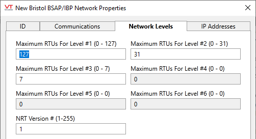
Maximum RTUs for Level #n
Bristol RTUs on BSAP networks can be configured up to 6 levels deep using the store and forward capabilities of the protocol. Use these fields to define the maximum number of RTUs for each level of the network from which the driver generates the network routing table (NRT) to send to the RTUs.
For a given level, the title will show how many RTUs can be accommodated, but the BSAP global address space is limited to 15 bits so the number of RTUs chosen per level can sometimes limit the number of RTUs on subsequent levels. In these situations, the lower levels will be set to 0 and grayed out to prevent editing their values.
In the example shown above, level 1 can have 127 RTUs (7 bits), level 2 can have up to 31 RTUs (5 bits) and level 3 can have up to 7 RTUs (3 bits) for a total of 15 bits of address space used. Because there is no more address space available, levels 4 through 6 are set to 0 and cannot be edited.
NRT Version # (1-255)
When the NRT is sent to the network by the driver, it includes a version number that is used by RTUs on the network to determine if the NRT has changed. The VTScada driver defaults this value to 1 when a network tag is created, but it’s value should be changed by incrementing it by 1 every time the maximum number of RTUs on any of the levels are changed. This will guarantee that the updated NRT generated by the driver is accepted and propagated by all RTUs on the network. If the version number is at its maximum value of 255 and the network configuration is changed, set it back to 1 and start the sequence again.
Bristol Network properties IP Addresses Tab
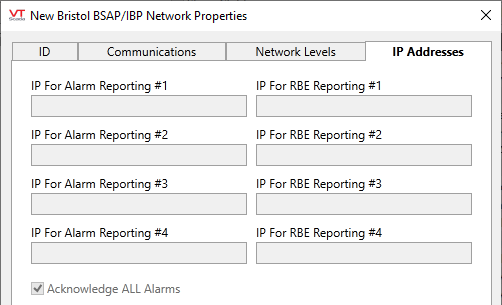
IP for Alarm Reporting #n
Configure IP addresses for ethernet connected RTUs that report their Alarms & Events. If configured, the IP addresses are sent to the RTU whenever the NRT is sent. All IP addresses must be in a.b.c.d format – i.e. names are not allowed.
In order for VTScada to be able to set the NRT and clock of an Ethernet connected RTU, the IP address of the VTScada server must be defined as one of the RTU’s NHP servers using the Bristol "Flash Configuration" utility in the LocalView or NetView programs.
RBE Reporting (Report By Exception Reporting) is not yet supported by VTScada.
Acknowledge All Alarms
Select this option to force VTScada to send an acknowledge to all received IPB alarm messages even if there is no alarm handler present (i.e. a Bristol Driver tag with the correct address) to accept and report the received alarms. This option can be useful for cleaning alarms out of a master RTU that is reporting alarms for old RTUs that may no longer exist.
The following widgets are available to display information about your Bristol Network tags:
Bristol Network Communication Messages Dialog
