TeleBUS Driver Tags
TeleBUS is a communications protocol that uses standard Modbus messages to retrieve history logs and audit information. Most TeleBUS messages consist of three Modbus exchanges:
- A command code is written to the command registers.
- The reply registers are read until a successful command has been confirmed.
- Data registers are read.
First, VTScada tells the TeleBUS RTU what information to look for by writing a command code and a meter run number to the command registers (which typically start with register 49500). The command codes indicate to the RTU the kind of data to load into the data registers. As an example, command code 801 can be used to retrieve the AGA-8 gas ratios. Along with the command code itself, we also supply the meter run number and the user/PIN combination.
After that command has been sent the RealFlo RTU will attempt to process it, loading the appropriate data into the data registers. It will then set the reply registers (typically starting with register 49505) to either a copy of the command code or to an error code. After sending a message VTScada’s TeleBUS driver continuously reads these command registers until it finds a match. The number and frequency of these checks can be tuned in the TeleBUS driver’s configuration folder.
Finally, assuming that the reply registers indicate that the operation has been completed successfully, VTScada reads the data registers and brings back the data.
RPC Service
The TeleBUS driver does not have its own RPC Service but rather uses the same one as its child Modbus driver. This is important to know if you are configuring custom server lists for your TeleBUS communications – you should look to create a new sever list based on the name of the child Modbus tag.
TeleBUS Application Properties
TeleBUSFailoverCount = 1
Number of consecutive errors before soft driver failover occurs
TeleBUSMaxReadLength = 125
Maximum block size for TeleBUS reads
The ID tab of every tag includes the same common elements: Name, Area, Description, and Help ID.
Name:
Uniquely identifies each tag in the application. If the tag is a child of another, the parent names will be displayed in a separate area before the name field.
You may right-click on the tag's name to add or remove a conditional start expression.
Area
The area field is used to group similar tags together. By defining an area, you make it possible to:
- Filter for particular tag groups when searching in the tag browser.
- Link dial-out alarm rosters to Alarm tags having a particular area.
- Limit the number of tags loaded upon startup.
- Filter the alarm display to show only certain areas.
- Filter tag selection by area when building reports.
When working with Parent-Child tag structures, the area property of all child tags will automatically match the configured area of a parent. Naturally, you can change any tag's area as required. In the case of a child tag, the field background will turn yellow to indicate that you have applied an override. (Orange in the case of user-defined types. Refer to Configuration Field Colors).
To use the area field effectively, you might consider setting the same Area for each I/O driver and its related I/O tags to group all the tags representing the equipment processes installed at each I/O device. You might also consider naming the Area property for the physical location of the tag (i.e. a station or name of a landmark near the location of the I/O device). For serial port or Roster tags, you might configure the Area property according to the purpose of each tag, such as System or Communications.
You may define as many areas as you wish and you may leave the area blank for some tags (note that for Modem tags that are to be used with the Alarm Notification System, it is actually required that the area field be left blank).
To define a new area, type the name in the field. It will immediately be added. To use an existing area, use the drop-down list feature. Re-typing an existing area name is not recommended since a typo or misspelling will result in a second area being created.
There is no tool to remove an area name from VTScada since such a tool is unnecessary. An area definition will exist as long as any tag uses it and will stop existing when no tag uses it (following the next re-start).
Description
Tag names tend to be brief. The description field provides a way to give each tag a human-friendly note describing its purpose. While not mandatory, the description is highly recommended.
Tag descriptions are displayed in the tag browser, in the list of tags to be selected for a report and also on-screen when the operator holds the pointer over the tag’s widget. For installations that use the Alarm Notification System, the description will be spoken when identifying the tag that caused the alarm.
The description field will store up to 65,500 characters, but this will exceed the practical limits of what can be displayed on-screen.
This note is relevant only to those with a multilingual user interface:
When editing any textual parameter (description, area, engineering units...) always work in the phrase editor. Any changes made directly to the textual parameter will result in a new phrase being created rather than the existing phrase being changed.
In a unilingual application this makes no difference, but in a multilingual application it is regarded as poor practice.
Help Search Key
Used only by those who have created their own CHM-format context sensitive help files to accompany their application.
TeleBUS Driver tag Communication Properties Tab
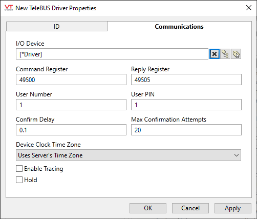
I/O Device
Select the Modbus driver that will communicate with the equipment.
The TeleBUS driver does not perform its own communications, but rather it organizes and sequences a number of Modbus messages that are sent through the standard Modbus driver. As a result, some communications settings may need to be set in the child Modbus driver instead of the TeleBUS driver itself.
Command Register & Reply Register
These allow you to specify the start of the command and reply registers if they are different from the standard RealFlo configuration.
User Number & User PIN
These can be configured in the RTU as a security measure. If this feature is not used both values should set to 1.
Confirm Delay
The number of seconds that the driver will wait between reads of the Reply Registers while waiting for acceptance of a command to be confirmed by the RTU. A shorter delay will result in faster poll times, while a longer delay will minimize bandwidth usage.
Max Confirmation Attempts
Is the number of times the Reply Registers are read without confirmation before the driver assumes that the command cannot be completed and declares a failed communication. This value should be tuned in conjunction with the Confirm Delay parameter – a long confirm delay and many attempts results in long timeouts in the event of a failed message, while a short confirm delay and few attempts may result in the driver giving up too soon before the RTU has a chance to confirm receipt of the command.
Device Clock Time Zone
The time zone of the RTU clock. This is used when logging time stamped information such as alarms, events and history.
Enable Tracing
If selected, a log file will be created under the Data\Trace folder of the application.
Hold
Select this to have I/O tags attached to the driver hold their last value in the event of a communication failure. If not selected, tags will have their value set to invalid on a communication failure.
The following widgets are available to display information about your tags:
