PLC Alarm Tag
Counted towards your tag license limit.
Use PLC Alarm tags where alarm logic is configured in the PLC rather than within VTScada. Alarm status and configuration is determined from the state of the PLC. The value of the PLC Alarm tag will be 1 when the alarm it monitors on the PLC is active and 0 otherwise, reflecting the state of the PLC.
By design, if communication with the PLC is lost after an alarm is reported, the PLC Alarm tag will continue to indicate the alarm until communication is reestablished and the alarm is cleared on the PLC. When using the PLC Alarm tag, the PLC is the alarm master, not VTScada.
If using this tag with a Control/CompactLogix or Micro800 PLC device (Rockwell devices), the alarm block name must be provided as a parameter to this tag, as well as the alarm type (Analog High, Digital, etc.). Using this information, the PLC Alarm tag will build all the necessary addresses. This note does not apply to other devices.
For customers using the legacy Oil & Gas Solutions layer, see: Deprecated PLC Alarm (OGS)
About Alarm Statuses
The status-related alarm controls issued from VTScada are to acknowledge, shelve or unshelve alarms. Limited support is also provided to enable or disable the alarm status (see following notes.) These status values are written to the PLC and read back into VTScada, where the current status of the PLC will be shown. The full set of PLC alarm status information, and how each status is handled by VTScada follows:
- Active / Normal:
This is a read-only status for VTScada. The value from the PLC tells the PLC Alarm tag whether it is in alarm or not, having value of 1 or 0 respectively.- Acked / Unacked:
VTScada will read this status, but is able to write only an Ack to the PLC. VTScada cannot write an Unack status.- Shelved / UnShelved:
VTScada will read this status and can also shelve or unshelve alarms within the PLC.
Both the PLC and VTScada support their own shelving time. In a Rockwell PLC, there is a single shelving time for a single alarm block, which is required to allow shelving at all. This shelving time would apply to a single digital alarm, or the set of all 6 analog alarms in a given block. If a shelving time is configured in VTScada for a given alarm, the alarm will be unshelved at the Internal PLC time, or the VTScada shelving time, depending on which happens first. This allows different alarms in the same block to be shelved for different amounts of time in VTScada only.- Suppressed / Unsuppressed:
Not supported by the PLC Alarm tag.
Auto unshelve causes the alarm to become unshelved.
Manual unshelve may cause some PLCs to unack alarms.
Alarm Configuration
Some users may want to issue configuration controls to the PLC via VTScada rather than use third-party software to do their PLC alarm configuration. The PLC alarm tag is able to configure Setpoint or Condition (for analog or digital alarms, respectively), Priority, Deadband, Delay and Disabled status. The PLC alarm tag has a custom widget for reading these configuration values as a reference, and outputting user-defined values to the correct address in the PLC.
To achieve this, the custom widget can be opened from the properties folder of the PLC Alarm tag. Control actions can be issued from the properties folder or from a page using the widget.
Rate of Change Alarms
VTScada will display positive values for both positive and negative rate of change values and setpoint on the alarm page. That is to say, if a tag’s value is rapidly decreasing, the positive ROC is not used, and the negative ROC will have a positive setpoint and positive value, with the implication that the rate of change being negative comes from the alarm type, rather than its value
VTScada conventionally interprets 1 as an active alarm and 0 as a normal status. Some PLCs work with opposite logic, 1 is a normal status and 0 is an active alarm. Using the Invert settings in the PLC Alarm tag will flip these values to make VTScada work compatibly with these devices. Some devices expect completely different values such as a discrete value (for example, 74) or a text value (for example, "Acknowledge"). You can create a custom property to write a custom value to the PLC.
PLCAlarm_Acknowledge_WriteValue property can be defined in two ways:
- A PLCAlarm_Acknowledge_WriteValue applicable to all PLC Alarm tags, it can be created in the Edit Properties Dialog of the Application Configuration.
- If you have multiple PLC Alarm tags requiring different custom Ack values, a PLCAlarm_Acknowledge_WriteValue can be defined in aContext Tags. Its custom Ack value is used by all its child PLC Alarm tags.
Custom Alarm Values are restricted to PLC Alarm tags with an Acked address. For any PLC Alarm tags that use custom Ack values, the Invert checkbox next to the Ack Address field has no effect.
Tag parameter expressions have "Optimize to only evaluate at tag initialization" selected by default.
Do not deselect this option for alarm parameter expressions. Do not use non-optimized expressions for alarm parameters.
The ID tab of every tag includes the same common elements: Name, Area, Description, and Help ID.
Name:
Uniquely identifies each tag in the application. If the tag is a child of another, the parent names will be displayed in a separate area before the name field.
You may right-click on the tag's name to add or remove a conditional start expression.
Area
The area field is used to group similar tags together. By defining an area, you make it possible to:
- Filter for particular tag groups when searching in the tag browser.
- Link dial-out alarm rosters to Alarm tags having a particular area.
- Limit the number of tags loaded upon startup.
- Filter the alarm display to show only certain areas.
- Filter tag selection by area when building reports.
When working with Parent-Child tag structures, the area property of all child tags will automatically match the configured area of a parent. Naturally, you can change any tag's area as required. In the case of a child tag, the field background will turn yellow to indicate that you have applied an override. (Orange in the case of user-defined types. Refer to Configuration Field Colors).
To use the area field effectively, you might consider setting the same Area for each I/O driver and its related I/O tags to group all the tags representing the equipment processes installed at each I/O device. You might also consider naming the Area property for the physical location of the tag (i.e. a station or name of a landmark near the location of the I/O device). For serial port or Roster tags, you might configure the Area property according to the purpose of each tag, such as System or Communications.
You may define as many areas as you wish and you may leave the area blank for some tags (note that for Modem tags that are to be used with the Alarm Notification System, it is actually required that the area field be left blank).
To define a new area, type the name in the field. It will immediately be added. To use an existing area, use the drop-down list feature. Re-typing an existing area name is not recommended since a typo or misspelling will result in a second area being created.
There is no tool to remove an area name from VTScada since such a tool is unnecessary. An area definition will exist as long as any tag uses it and will stop existing when no tag uses it (following the next re-start).
Description
Tag names tend to be brief. The description field provides a way to give each tag a human-friendly note describing its purpose. While not mandatory, the description is highly recommended.
Tag descriptions are displayed in the tag browser, in the list of tags to be selected for a report and also on-screen when the operator holds the pointer over the tag’s widget. For installations that use the Alarm Notification System, the description will be spoken when identifying the tag that caused the alarm.
The description field will store up to 65,500 characters, but this will exceed the practical limits of what can be displayed on-screen.
This note is relevant only to those with a multilingual user interface:
When editing any textual parameter (description, area, engineering units...) always work in the phrase editor. Any changes made directly to the textual parameter will result in a new phrase being created rather than the existing phrase being changed.
In a unilingual application this makes no difference, but in a multilingual application it is regarded as poor practice.
Help Search Key
Used only by those who have created their own CHM-format context sensitive help files to accompany their application.

I/O configuration of a PLC Alarm tag
The I/O Tab includes properties used to identify and establish a connection to the communication driver tag being used to exchange data with your physical I/O device (e.g. PLC or RTU), or to the polling driver responsible for determining the order and rate at which data polls will occur.
I/O Device
Select the communication driver tag from which data will be read.
By default, the tag will look for an ancestor or sibling tag that is a device driver (*Driver). If none is found, the text "--Missing--" will be displayed. If more than one equally qualified tags are found, "--Error: Multiple Drivers--" will be displayed. The tag button to the right of the field opens the tag browser, from which you can either select an existing communication driver tag or add a new one. The X button will clear the field. Right-clicking on a tag in the field will open a dialog with which you can add or remove a Snapshot Expression or open a selected driver's properties dialog.
PLC Type
Choose between "Control/CompactLogix or Micro800 PLC" (addresses are pre-configured) or "Custom PLC" (addresses must be provided).
Alarm Type
A selection of Digital, Analog High, Analog Low, etc.
Required when configuring a Rockwell driver. For custom PLCs this is used as a label to distinguish between alarm types on the alarm page and to determine the behavior of the tag based on whether it is an analog or digital alarm.
PLC Alarm Block Name
If a PLC alarm block name is given, it will preface the address parameters. If there is no alarm block name given, the addresses are complete.
For Rockwell drivers, this is the folder in the PLC that holds all the addresses of the alarm block registers. This is an address in the form, MyProgram:MyAnalogAlarm, under which the relevant alarms will be located. (For example, MyProgram:MyAnalogAlarm.HiHiEnable)
Privilege
Select a custom security privilege
Scan Interval
Provide the frequency, measured in seconds, that the device should be scanned for new data. If the I/O Device is a Polling driver, which provides its own scan interval, then this field will not accept data.
Questionable Data
Use the Questionable Data parameter to flag this tag’s data in the event that you suspect the values it is reporting might not be accurate, or when this tag has initially been created and you wish to ensure that its data is marked for extra monitoring.
PLC Alarm Properties Addresses tab

Address configuration for custom PLC alarms
For Control/CompactLogix or Micro800 PLC, these show the pre-configured addresses based on the alarm type. (Addresses cannot be modified.)
For a Custom PLC, use this to input the PLC alarm’s function addresses. An address assist is provided as a convenience. Only the Active address is required for the PLC alarm tag to work, but each address provides additional functionality and information.
Many values are also invertible. If the "Invert" checkbox next to any address is checked, then VTScada inverts the value read from that address or inverts then writes the value to that address. This allows correct communication with PLCs that use values opposite to those that VTScada expects. For example, VTScada expects a value of 1 from a PLC as an active alarm, but some PLCs use a value of 0 for their active alarm. By reading the PLC's 0 as a 1, VTScada correctly registers the alarm. If a custom property is being used to specify a custom value, the Invert checkbox will have no effect.
Active address (Read, Invertible):
Used to read the digital status of the PLC alarm, 1 if it is in alarm, 0 if it is not.
Value address (Read):
Used to read the value in the PLC, used to determine its active status internally.
Acked address (Read, Invertible):
Used to read the acked status of the alarm. 1 is acknowledged, 0 is not.
Ack address (Write, Invertible):
Used to set the alarm to be acknowledged.
Disabled address (Read, Invertible):
Used to read the disabled status of the alarm. 1 is disabled, 0 is not.
Disable address (Write, Invertible):
Used to set the alarm to be disabled.
Enable address (Write, Invertible):
Used to set the alarm to be enabled.
Shelved address (Read, Invertible):
Used to read the shelved status of the alarm. 1 is shelved, 0 is not.
Shelve address (Write, Invertible):
Used to set the alarm to be Shelved.
Unshelve address (Write, Invertible):
Used to set the alarm to be Unshelved.
Setpoint address (Read/Write):
Used to set the alarm’s setpoint (Analogs only). Also read for display.
Priority address (Read/Write):
Used to set the alarm’s priority. Also read for display.
Deadband address (Read/Write):
Used to set the alarm’s deadband. Also read for display.
Delay address (Read/Write):
Used to set the alarm’s delay. Also read for display.
Condition address (Read/Write, Invertible):
Used to set the alarm’s condition (digitals only). Also read for display.
Not all addresses need be configured for a given PLC alarm. If there are not separate Acked/Ack bits in a given PLC, it is only required to configure one of them with the single read/write acknowledging bit. Similarly, for Disabling and Shelving, a single read/write address can be configured rather than using all 3 addresses, depending on the PLC in use. The table below shows the read/write behavior for various address configurations, using Disabled/Disable/Enable as an example. The same logic applies to the shelving/unshelving addresses.
| Available Addresses | Read disabled status from (Address : Value) |
For disabling write to (Address : Value) |
For enabling write to (Address : Value) |
|||
|---|---|---|---|---|---|---|
|
Disabled : 1 | Disabled : 1 | Disabled : 0 | |||
|
Disable : 1 | Disable : 1 | Disable : 0 | |||
|
Enable : 0 | Enable : 0 | Enable : 1 | |||
|
Disabled : 1 | Disable : 1 | Disable : 0 | |||
|
Disabled : 1 | Enable : 0 | Enable : 1 | |||
|
N/A | N/A | N/A | |||
|
Disabled : 1 | Disable : 1 | Enable : 1 |
PLC Alarm properties Alarm Setup tab
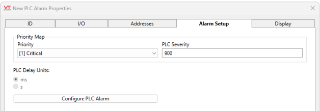
Alarm Setup configuration of a PLC Alarm tag
Priority
For Control/CompactLogix or Micro800 alarms, there are two parts to priority mapping: The selection of the VTScada Alarm Priority, and the selection of the corresponding alarm severity value in the PLC.
In the case of a Custom PLC there are two methods by which to set the VTScada alarm priority, depending on the existence of a priority address. If a priority address is given, we read the priority of the alarm from the PLC through the priority map. If no priority address is given, the PLC does not govern the alarm priority, and we must assign a priority to the alarm internally. This is done through a priority selection droplist.
PLC Delay Units
The internal units of a custom PLC may be in seconds or milliseconds, while the delay of the PLC alarm tag is written and displayed in seconds. This configuration allows proper configuration (and therefore display in VTScada) of the delay from the PLC.
Configure PLC Alarm
Opens the following dialog...
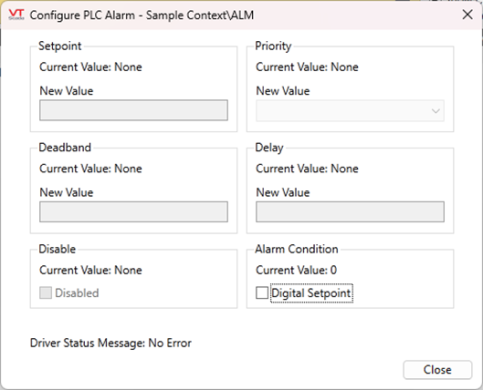
PLC Alarm properties Configuration dialog
Properties you configure in this dialog are read from and written to the PLC.
Controls on this tab write to the PLC immediately upon change.
I/O configuration of a PLC Alarm tag
Setpoint
The setpoint for an analog alarm.
Priority
Use Priority drop-down tool to select the priority of the alarm that will be triggered for this tag. The available priorities are:
None 0 - Event 1 - Critical Alarm 2 - High Alarm 3 - Warning Alarm 4 - Notice Alarm
Deadband (Not relevant to digital alarms)
The Deadband field specifies how far the triggering value must return into the safe (normal) zone before the alarm is no longer considered active. Deadband values are used in systems where analog values fluctuate often, sometimes providing a false data reading.
Delay
There is a conversion that must occur between VTScada and the PLC. The delay in the PLC is measured in microseconds, while the standard VTScada delay is in seconds. PLC Delay Units applies a factor to the incoming/outgoing delay.
Disable
Use the Disable Alarm checkbox field to disable or enable this Alarm tag. Unchecked = 0 (not disabled) and checked = 1 (disabled). This feature is typically used in situations such as when routine maintenance is being performed. In such a situation, an alarm can be disabled until the maintenance is complete and communications are reestablished, thus avoiding false alarms.
Alarm Condition - Digital Setpoint
This setting is only used when the Alarm Type is set to Digital Alarm. Check Digital Setpoint to set the alarm condition value at the Condition Address provided in the Address tab. If no address is provided, the default value is 1.
Please note that the Invert setting applies here. If no address is provided and Invert is checked the default value becomes 0.
PLC Alarm properties Display tab
(Digital alarm version shown)
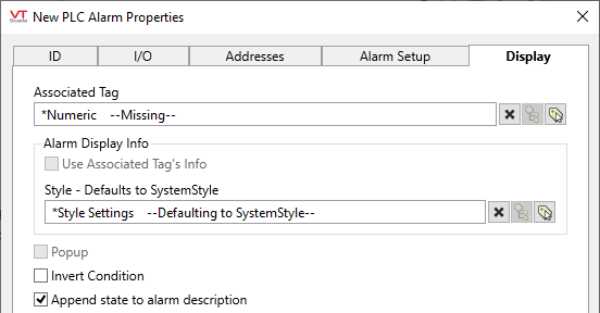
Associated Tag
If an I/O tag is reading a specific value from the PLC while the PLC alarm block is alarming on that value, it makes sense for the name of the alarm in VTScada to match the name of the I/O tag, rather than the name of the PLC alarm tag. Therefore, the alarm record will contain the name of the associated value I/O tag, which is obtained by setting the Associated Tag parameter of each PLC Alarm tag to be the tag from which the source value is read. The alarm record will show the description, units, and area of the associated tag, allowing the PLC Alarm tag to behave like a built-in alarm of an I/O tag.
Typically, this is done by making the PLC Alarm tag a child of the associated I/O tag.
Use Associated Tag's Info
Deselect if you have an associated tag, but do not want to use information from that tag for display purposes.
Style
When this tag is represented on screen by widgets that can use a Style Settings tag, you can save development time by choosing the Style Settings tag that holds the correct display configuration for this tag instance. (See: Style Settings Tags)
The default configuration will search for the first ancestor or then sibling tag of the Style Settings type. If there is none, it will use System Style, which is the default style tag that is automatically part of every new VTScada application.
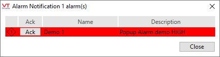
Popup
If the configuration variable AlarmPopupsEnable is set to 1, then selecting this option will result in a pop-up dialog being displayed whenever the alarm is triggered. The variable can be set using a check box within the Application Configuration dialog, Alarms tab.
The pop-up will display the names of all active alarms for which the Pop-up option has been selected. As alarms are acknowledged, they will be removed from the pop-up. Should all the alarms be acknowledged while the pop-up is displayed, it will close. You may close the pop-up at any time by selecting the Close button. The pop-up will not be displayed again until a fresh alarm event occurs.
Append state to alarm description (Digital alarm only)
When selected, VTScada will append the text used for the state of the tag, as taken from the Off Text and On Text fields in the associated tag’s I/O tab, to the alarm message.
Engineering Units (Analog alarms only)
Enter the units that should be displayed with the alarm.
