Campbell Scientific Array Driver
Not counted towards your tag license limit.
Create a Campbell Scientific Array driver tag to enable communications between VTScada and Campbell Scientific data loggers such as the model CR510 and CR10X units, which are running the older, array-based operating system.
Campbell Scientific Array I/O Addressing
Campbell Scientific Error Codes
Related Application properties
The following properties hold additional configuration parameters for your Campbell Scientific Array driver:
CampbellProgressWindow - When enabled, a progress window will be displayed when the Campbell devices are downloading data. This will typically be enabled (i.e. set to 1) on larger systems using dedicated servers or disabled (i.e. set to 0) on systems using a single PC to act as a combination server & user workstation.
CampbellSharedRPC - When enabled, all Campbell devices share an RPC Service. This enables all Campbell device drivers to run on the same RPC server. If any should fail, then control for the entire group shifts. drivernameSharedRPC properties are stored in Settings.Startup, not Settings.Dynamic. Changes require a restart of the application in order to take effect.
CampbellTestMode - If true, data for Campbell devices should be read from a file, and not from the device. Should not be enabled unless testing specific functions of the driver.
CampbellCRSendCount - Sets the number of carriage returns (Enter keys) that should be sent when connecting to the Campbell devices. Normally, this should be set to 1.
CampbellCRSendWaitTime - Sets the amount of time (in seconds) VTScada will wait after each carriage return (Enter key) sent.
CampbellCRLFWaitTime - Sets the amount of time (in seconds) VTScada will wait for the asterisk character after CRs have been sent when initializing communication with the device.
CampbellCheckSig - If true, VTScada will check the signature bytes sent after each command response to the Campbell device. This should typically be enabled unless there is an application specific reason to disable it.
CampbellSearchWindowSize - Used for tuning by VTScada when searching for timestamps in the Campbell memory bank. The larger this window size, the quicker the search will be but the longer the download will be. The default of 2000 should be used in most circumstances. Valid values range from 100-65535.
CampbellReadAllFirstTime - When set (1), causes the driver to read all logged data in the device when communication is first established rather than new data only. This will be in effect only when the driver is created and connected to the device for the first time.
CampbellReadOnStart - When set (1), forces the driver to do a read of any new data in the RTU as soon as the driver is started instead of waiting until the first time it is polled.
CampbellNoLastMatchRequired - When not set (0), the driver will attempt to obtain an exact match of values for read-alignment of last readings with new readings. Can normally be left at its default value of 1.
Campbell Scientific Array properties ID tab
The ID tab of every tag includes the same common elements: Name, Area, Description, and Help ID.
Name:
Uniquely identifies each tag in the application. If the tag is a child of another, the parent names will be displayed in a separate area before the name field.
You may right-click on the tag's name to add or remove a conditional start expression.
Area
The area field is used to group similar tags together. By defining an area, you make it possible to:
- Filter for particular tag groups when searching in the tag browser.
- Link dial-out alarm rosters to Alarm tags having a particular area.
- Limit the number of tags loaded upon startup.
- Filter the alarm display to show only certain areas.
- Filter tag selection by area when building reports.
When working with Parent-Child tag structures, the area property of all child tags will automatically match the configured area of a parent. Naturally, you can change any tag's area as required. In the case of a child tag, the field background will turn yellow to indicate that you have applied an override. (Orange in the case of user-defined types. Refer to Configuration Field Colors).
To use the area field effectively, you might consider setting the same Area for each I/O driver and its related I/O tags to group all the tags representing the equipment processes installed at each I/O device. You might also consider naming the Area property for the physical location of the tag (i.e. a station or name of a landmark near the location of the I/O device). For serial port or Roster tags, you might configure the Area property according to the purpose of each tag, such as System or Communications.
You may define as many areas as you wish and you may leave the area blank for some tags (note that for Modem tags that are to be used with the Alarm Notification System, it is actually required that the area field be left blank).
To define a new area, type the name in the field. It will immediately be added. To use an existing area, use the drop-down list feature. Re-typing an existing area name is not recommended since a typo or misspelling will result in a second area being created.
There is no tool to remove an area name from VTScada since such a tool is unnecessary. An area definition will exist as long as any tag uses it and will stop existing when no tag uses it (following the next re-start).
Description
Tag names tend to be brief. The description field provides a way to give each tag a human-friendly note describing its purpose. While not mandatory, the description is highly recommended.
Tag descriptions are displayed in the tag browser, in the list of tags to be selected for a report and also on-screen when the operator holds the pointer over the tag’s widget. For installations that use the Alarm Notification System, the description will be spoken when identifying the tag that caused the alarm.
The description field will store up to 65,500 characters, but this will exceed the practical limits of what can be displayed on-screen.
This note is relevant only to those with a multilingual user interface:
When editing any textual parameter (description, area, engineering units...) always work in the phrase editor. Any changes made directly to the textual parameter will result in a new phrase being created rather than the existing phrase being changed.
In a unilingual application this makes no difference, but in a multilingual application it is regarded as poor practice.
Help Search Key
Used only by those who have created their own CHM-format context sensitive help files to accompany their application.
Server List
Select (or create) a named server list.
Campbell Scientific Array properties Settings tab
The Settings tab includes properties
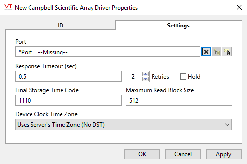
Port
The port used to communicate with the data logger. The driver supports the use of directly-connected serial ports, modem-connected serial ports, TCP/IP ports and UDP/IP ports.
Response Timeout
This is the number of seconds the driver tag will wait for a response message from the device. If the driver does not receive a response within the defined length of time it will try again according to the following parameter.
Retries
The number of times to retry a message before declaring an error.
Use only if the driver is connected to a device that uses a serial port or a UDP/IP port that is configured to be polled. When connected directly to a device using TCP/IP, this value should normally be set to 0 since TCP/IP is a guaranteed message delivery protocol.
For unreliable communications, such as radio, set to 3 or 4.
Hold
Select this to have I/O tags attached to the driver hold their last value in the event of a communication failure. If not selected, tags will have their value set to invalid on a communication failure.
Final Storage Time Code
Defines the final storage time format used when programming the data logger. Note that, if the devices is using multiple storage arrays, the driver expects all arrays to use the same format. The time code is defined as follows, where "x" is defined as "don’t care" and is normally entered as a 0:
- xxx1 Seconds (with resolution of 0.125 sec.)
- xx1x Hour-Minute
- xx2x Hour-Minute, 2400 instead of 0000
- x1xx Julian Day
- x2xx Julian Day, previous day during first minute of new day
- 1xxx Year
Any combination of Year, Day, Hour-Minute, and Seconds is possible (e.g., 1011: YEAR, Julian Day, Hour-Minute, Seconds).
Maximum Read Block Size
The maximum number of words that will be read from the site RTU on each transfer when retrieving logged data from a device using the "F" command. (Refer to the addressing section for more details.) Data transfers larger than this size require multiple read operations. Decreasing this value reduces the chance of communications errors by using smaller packets, but it will also increase the transmission time for large-record polls. Recommended values for this setting are 512 for direct serial and TCP/UDP connected devices and 128 or 256 for modem connected devices. If your connection is subject to system noise, you may want to use smaller settings to increase communication reliability.
Device Clock Time Zone
The time zone of the clock in the data logger. This is used to correct the time-stamped values read from the device by VTScada for storage in its historian using UTC format. Regardless of the time zone selected with this option, the driver assumes that the device does NOT adjust its clock for day-light savings time (DST).
- Uses Server Time Zone (no DST) - assumes that the device is in the same time zone as the server.
- Device Clock In UTC - the clock in the device is set to UTC.
- Actual Time Zone - select the actual time zone, in which the device is located.
The following widgets are available to display information about your Campbell Scientific Array driver tags:
