
The Grundfos Control MPC is a multi-purpose controller that will work with Modbus RTU (CIM 200), Modbus TCP (CIM 500), UDP/IP BACnet and MSTP BACnet. (MSTP BACnet only if used on foreign networks to which you connect via IP)
A selection of models is available for both the Modbus profile and the BACnet profile.
This one tag contains the child tags needed to run the system in any of the standard closed-loop operating modes (pressure, temperature, flow). Additional child IO tags can be added to match the exact sensor configuration, where they will display on the inputs tab.
Grundfos Dedicated Controls Event Log
The ID tab of every tag includes the same common elements: Name, Area, Description, and Help ID.
Name:
Uniquely identifies each tag in the application. If the tag is a child of another, the parent names will be displayed in a separate area before the name field.
You may right-click on the tag's name to add or remove a conditional start expression.
Area
The area field is used to group similar tags together. By defining an area, you make it possible to:
- Filter for particular tag groups when searching in the tag browser.
- Link dial-out alarm rosters to Alarm tags having a particular area.
- Limit the number of tags loaded upon startup.
- Filter the alarm display to show only certain areas.
- Filter tag selection by area when building reports.
When working with Parent-Child tag structures, the area property of all child tags will automatically match the configured area of a parent. Naturally, you can change any tag's area as required. In the case of a child tag, the field background will turn yellow to indicate that you have applied an override. (Orange in the case of user-defined types. Refer to Configuration Field Colors).
To use the area field effectively, you might consider setting the same Area for each I/O driver and its related I/O tags to group all the tags representing the equipment processes installed at each I/O device. You might also consider naming the Area property for the physical location of the tag (i.e. a station or name of a landmark near the location of the I/O device). For serial port or Roster tags, you might configure the Area property according to the purpose of each tag, such as System or Communications.
You may define as many areas as you wish and you may leave the area blank for some tags (note that for Modem tags that are to be used with the Alarm Notification System, it is actually required that the area field be left blank).
To define a new area, type the name in the field. It will immediately be added. To use an existing area, use the drop-down list feature. Re-typing an existing area name is not recommended since a typo or misspelling will result in a second area being created.
There is no tool to remove an area name from VTScada since such a tool is unnecessary. An area definition will exist as long as any tag uses it and will stop existing when no tag uses it (following the next re-start).
Description
Tag names tend to be brief. The description field provides a way to give each tag a human-friendly note describing its purpose. While not mandatory, the description is highly recommended.
Tag descriptions are displayed in the tag browser, in the list of tags to be selected for a report and also on-screen when the operator holds the pointer over the tag’s widget. For installations that use the Alarm Notification System, the description will be spoken when identifying the tag that caused the alarm.
The description field will store up to 65,500 characters, but this will exceed the practical limits of what can be displayed on-screen.
This note is relevant only to those with a multilingual user interface:
When editing any textual parameter (description, area, engineering units...) always work in the phrase editor. Any changes made directly to the textual parameter will result in a new phrase being created rather than the existing phrase being changed.
In a unilingual application this makes no difference, but in a multilingual application it is regarded as poor practice.
Help Search Key
Used only by those who have created their own CHM-format context sensitive help files to accompany their application.
Grundfos Control MPC: Settings tab
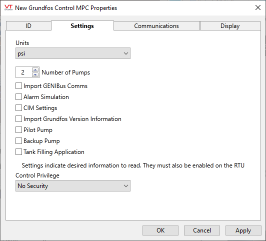
Units
The device may be used for a variety of control modes, covering measurement of flow, temperature, and pressure. Use this to ensure that the display matches the purpose of the controller and your preferred system of units.
Number of Pumps
Select a number from 0 to 6, matching your system.
Import GENIBus Comms
Enable to view GENIbus communications for detecting problems between the controller and the pumps.
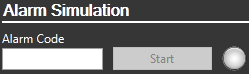
Alarm Simulation
Enable to use the alarm simulation tool in the controller. This will be added to the Summary tab of the automatically-generated station page. To enable the Start button, provide an alarm code in the space provided.
CIM Settings
Enable to view and edit the CIM card settings (Communication Interface Module). Needed only for configuration.
Import Grundfos Version Information
Enable to display Grundfos-specific information on the inputs tab.
Pilot Pump
Select this option if the system contains a dedicated pilot pump for its controls.
Backup Pump
Enable if the system contains a dedicated backup pump for its controls
Tank Filling Application
Enable if the controller is configured for a tank-filling application, in order to allow access to the extra setpoints that are needed.
Control Privilege
Select a custom security privilege
Grundfos Control MPC: Communications tab
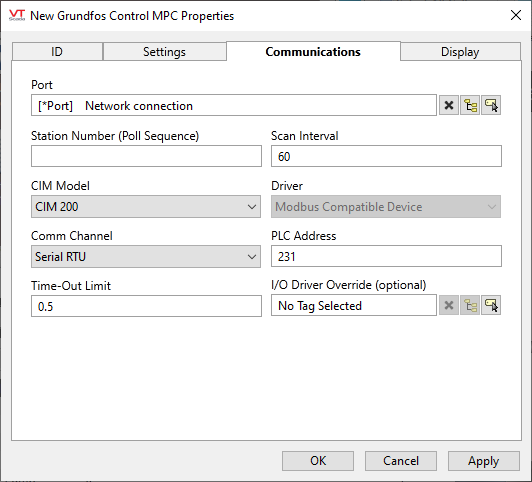
Port
Select the TCP/IP or Serial Port tag that is to be used for communication with the equipment. The ancestor port is selected automatically if this tag is created as a child of a port. If there is a sibling port and no ancestor port, then the sibling port will be selected automatically.
Station Number (Poll Sequence)
Used by the built-in Polling Driver Tags. Use the Poll Sequence Number field to specify a number that identifies this polling driver's place in the polling sequence for the identified poll group.
For example, if you have 5 polling drivers, each of which is associated with a different communication driver (e.g. Modbus1, Modbus2, etc.), and all 5 polling drivers have the same poll group identified (in their Poll Group Name property), you must enter a number from 1 to 5 for each of the polling drivers to determine the order in which the 5 communication drivers belonging to the poll group will be polled.
Scan Interval
Used by the built-in Polling Driver. The amount of time (in seconds) between requests for data from this Polling Driver tag to the I/O device with which it is associated.
CIM Model
Choose between models CIM 200, CIM 250 GSM, CIM 250 GPRS, CIM 300, CIM 500 Modbus or CIM 500 BACnet.
Driver
Configured automatically in response to your choice of CIM model.
Comm Channel (Modbus compatible profile)
Serial RTU, Open Modbus TCP/IP or Open Modbus TCP
PLC Address (Modbus compatible profile)
The standard port is 231, but may be overridden if necessary.
Network Type (Routing) (BACnet profile)
Set automatically based on your selection of CIM model
Device Node and Device Network Number (BACnet profile)
When operating in foreign network mode of BACnet, specify the network number that the device is on, and specify the device node number on that network.
Time-Out Limit
Set the receiver time-out limit in seconds or fractions of a second. This is the length of time that this driver should wait for a reply from the PLC or RTU.
I/O Driver Override (optional)
The device typically uses a built-in Modbus Compatible Device Driver, or BACnet Driver based on your choice of CIM, but you may use this tool to select another.
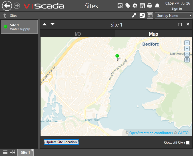
The Display tab is used to define the placement (latitude and longitude) of the Polling Driver station. Decimal values should be used rather than degrees, minutes and seconds.
Latitude and Longitude
Holds location coordinates for this tag, thereby allowing it to be represented on a Site Map page.
Custom Details Page
If a custom details page has been created for this context tag, then that page should be selected here. If there is no custom details page, then operators will see the standard Site Details page upon clicking the pin for this tag in a Site Map.
Advanced Configuration:
The default page selection dialog has a filter for "all pages" or "site pages", meaning those that take a site tag as the first parameter.
You can add either of the following two properties in the Edit Properties page of the Application Configuration dialog to restrict this filter:
LimitPageListToSitesPages
System section. Set to 1 (TRUE) to prevent access to the "all pages" option in the page selection dialog for all users.
LimitPageListToSitesPagesIfRealmUser
System section. Set to 1 (TRUE) to prevent access to the "all pages" option in the page selection dialog if the user belongs to a security group.
Custom Map Icon
If a custom map icon widget has been defined, you can select it here. That icon will then be used instead of the standard pin when this tag is represented on a Site Map page. If there is no custom map icon, then the standard pin will be used.
Site List Display
Assuming that this tag has site properties, it will be included in the list of a Sites page. What will happen when an operator clicks on this tag in that list depends on the Site List display choice, and on whether any of this tag's children are I/O tags.
- Display as Site: A click will open the Site Details page as a pop-up.
- Display as Folder: A click will leave focus on the Sites page, but the list will now show the child tags of this site.
- Exclude: This tag should not be shown in the Sites page list.
Map Zoom Level
If Automatic is chosen (the default) then when a map is opened, showing only this site, it will zoom to level 15, which shows only the immediate surroundings. You may select any value between 18 (the closest possible level) and 2 (showing the entire globe).
Default zoom level.
The following widgets are supported for your Grundfos Control MPC.
(It would be unusual to draw any of the component widgets on its own, therefore they are not described here.)
| Alarm Priority Box | Alarm Priority Icon |
| Alarm List | Site Icon Widget |
| Site Summary Widget | Site Alarm List |
| Tag List Widget | Draw HDV Widget |
