Polling Driver Tags
Not counted towards your tag license limit.
Polling driver tags are designed for use in telemetry applications where communication links may be costly, either in terms of time or money.
Reference Notes:
The Polling driver tag provides the following features:
- The ability to poll multiple stations or I/O devices in a pre-determined order and at a fixed time interval.
- The ability to switch to fast-polling mode of selected sites on demand. See Fast Scan Widget.
- Provides a simple grouping of I/O tags on a single display.
- Navigate to a station page using F11 or F12.
Polling driver tags are not required for Data Flow RTU driver tags because those have a polling feature built-in.
Each polling driver should be attached to a unique driver. These may share a common port.
Because Poll Drivers use the same RPC service as their communication driver, it is important to ensure that all communication drivers within the same Polling Group are using the same server list.
Polling drivers should be configured to stand between a communications driver tag and the I/O tags. Their function is to control the order and the frequency of data transfer between the I/O tags and the remote equipment via the communication driver tag.
When data is written from an output tag, it is immediately passed to the Polling driver tag and then on to the associated communication driver tag. Following each write, all I/O addresses will be read immediately so that feedback need not wait for the next polling cycle.
About Scan Intervals
All input tags associated with a Polling driver will use the Scan Interval configured for the Polling driver rather than their configured scan rate. The minimum Scan Interval is actually 1 second. If the Scan Interval is set to 0, it will scan as close to 1 second as possible, limited by how quickly scans are completed. If the Scan Interval is not set, it will default to 60 seconds. You cannot poll by External Trigger only. However, you can set an extremely large Scan Interval to minimize the number of nuisance scans.
The highest Scan Interval you can set is 2,147,483,647 seconds. That is roughly equivalent to once every 68 years.
The actual scan interval is limited by the speed of communication. If it takes 10 seconds to poll a station and the scan interval is less than 10 seconds, the driver will poll every 10 seconds.
If you require scan intervals measured in fractions of a second, configure those directly within your I/O tags and do not use a Polling driver to control timing.
See: Polling Groups and Scan Intervals
Alarming
When polling fails-over from the primary server to a backup, VTScada automatically generates an alarm with priority 3 (warning). You may control this using three application properties as follows:
- PollDriverAlarmPriority. Defaults to 3 - Warning.
- PollDriverAlarmDisable. Defaults to FALSE. In spite of the name, this property will decommission the alarm rather than disable it when set to TRUE.
- PollDriverAlarmOnDelay. Defaults to 60 seconds. Avoids nuisance alarms from transient network issues.
A common need is to create an alarm that will be triggered, not on the first failure, but only after x consecutive polling cycles have failed. This can be done using an expression in an Alarm tag, created as a child of the Polling driver. You will need to know the following:
- [*Driver]\LastTime will return the time stamp of the parent Polling driver's last successful poll.
- Time stamps are measured in seconds since January 1, 1970. (Standard computer time stamp.)
- Today()*86400 will give you the number of seconds from January 1, 1970 to midnight last night.
- Now(60) will give you the number of seconds from midnight to the most recent minute, updating once a minute at the minute mark.
Combining that information, you can create the following expression to find the time since the last successful poll, updating on each poll and on the minute mark:
Today()*86400 + Now(60) - [*Driver]\LastTime
If your polling rate is two minutes (120 seconds) and you want an alarm after five unsuccessful polls (5 * 120 = 600), then your alarm expression becomes:
Today()*86400 + Now(60) - [*Driver]\LastTime >= 600
Learn more about expressions here: Expressions
Pressing either F11 or F12 will open the Station Number dialog:
Polling Groups and Scan Intervals
The ID tab of every tag includes the same common elements: Name, Area, Description, and Help ID.
Name:
Uniquely identifies each tag in the application. If the tag is a child of another, the parent names will be displayed in a separate area before the name field.
You may right-click on the tag's name to add or remove a conditional start expression.
Area
The area field is used to group similar tags together. By defining an area, you make it possible to:
- Filter for particular tag groups when searching in the tag browser.
- Link dial-out alarm rosters to Alarm tags having a particular area.
- Limit the number of tags loaded upon startup.
- Filter the alarm display to show only certain areas.
- Filter tag selection by area when building reports.
When working with Parent-Child tag structures, the area property of all child tags will automatically match the configured area of a parent. Naturally, you can change any tag's area as required. In the case of a child tag, the field background will turn yellow to indicate that you have applied an override. (Orange in the case of user-defined types. Refer to Configuration Field Colors).
To use the area field effectively, you might consider setting the same Area for each I/O driver and its related I/O tags to group all the tags representing the equipment processes installed at each I/O device. You might also consider naming the Area property for the physical location of the tag (i.e. a station or name of a landmark near the location of the I/O device). For serial port or Roster tags, you might configure the Area property according to the purpose of each tag, such as System or Communications.
You may define as many areas as you wish and you may leave the area blank for some tags (note that for Modem tags that are to be used with the Alarm Notification System, it is actually required that the area field be left blank).
To define a new area, type the name in the field. It will immediately be added. To use an existing area, use the drop-down list feature. Re-typing an existing area name is not recommended since a typo or misspelling will result in a second area being created.
There is no tool to remove an area name from VTScada since such a tool is unnecessary. An area definition will exist as long as any tag uses it and will stop existing when no tag uses it (following the next re-start).
Description
Tag names tend to be brief. The description field provides a way to give each tag a human-friendly note describing its purpose. While not mandatory, the description is highly recommended.
Tag descriptions are displayed in the tag browser, in the list of tags to be selected for a report and also on-screen when the operator holds the pointer over the tag’s widget. For installations that use the Alarm Notification System, the description will be spoken when identifying the tag that caused the alarm.
The description field will store up to 65,500 characters, but this will exceed the practical limits of what can be displayed on-screen.
This note is relevant only to those with a multilingual user interface:
When editing any textual parameter (description, area, engineering units...) always work in the phrase editor. Any changes made directly to the textual parameter will result in a new phrase being created rather than the existing phrase being changed.
In a unilingual application this makes no difference, but in a multilingual application it is regarded as poor practice.
Help Search Key
Used only by those who have created their own CHM-format context sensitive help files to accompany their application.
Polling Driver properties I/O tab
The I/O tab for the Polling Driver tag consists of properties used to identify the communication driver tag to be associated with this polling driver, and to establish the poll group, the I/O device's sequence in the poll, and the interval at which the equipment associated with the communication driver tag should be polled for data.

I/O Device
The I/O Device field enables you to specify the communication driver tag for which this polling driver will set the scan rate.
The I/O Device field can be used to associate this tag with a new or existing communication driver tag using the tag browser button. The button opens the Tag Browser, which displays only the existing communication driver tags for your application, and enables you to create a new communication driver tag using its New button.
Poll Group Name
Optional. If you have several Polling Drivers with similar configurations and especially if those drivers use the same port (possibly a radio) you may create an association between them by creating and assigning the same group name to all. There are several use-cases for this, as described in Polling Groups and Scan Intervals.
Poll Sequence Number
Relevant only if you have used the same Poll Group Name for several Polling Drivers, and if those drivers are configured with the same Scan Interval and Delay After Scan.
Because the interval and delay are the same, all drivers are placed on the group's "to-be-polled" list at the same time. The Poll Sequence Number specifies this driver's place in the sequence for the identified group. See: Polling Groups and Scan Intervals
Scan Interval
Measured in seconds with an actual minimum equal to the number of seconds it takes to poll or 1 second, whichever is greater. A value of 0 will poll at this minimum rate.
This setting is required. If there is no value, it will poll every 60 seconds by default.
Scan Interval Offset
Measured in seconds. Sets a delay after the Scan Interval that must pass before the driver is added back to the "to-be-polled" list. For example, if the Scan Interval is 10 and the delay is 2 (both measured in seconds) then the driver will be added back into the to-be-polled list at the 2, 12, 22, 32... marks, assuming that it takes less than 10 seconds to complete the poll. (10 second interval plus 2, not 12 second intervals of 12, 24, 36...)
See: Polling Groups and Scan Intervals
External Poll Trigger
May be linked to any tag or expression that transitions from a 0 or invalid state to a 1-state to trigger a poll.
Using a Trigger tag is a Best Practice. If you want to schedule polling to occur on a given schedule or in response to an operator’s command.
A couple of important notes about External Poll Triggers:
- An external poll signal will not cause a poll to occur if polling is disabled, or if fast scan mode is enabled.
- You cannot poll by trigger only. You must have a Scan Interval, but you can make it very large. (Max 2,147,483,647, roughly 68 years)
Disable Polling
Use to disable or re-enable the polling cycle for this poll driver. This does not mean that reads or writes are disabled because only the polling cycle is affected. A Toggle Polling Button widget can be drawn in your application to allow operators to change this value at need.
The Display tab is used to define the placement (latitude and longitude) of the Polling Driver station. Decimal values should be used rather than degrees, minutes and seconds.
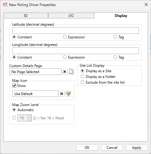
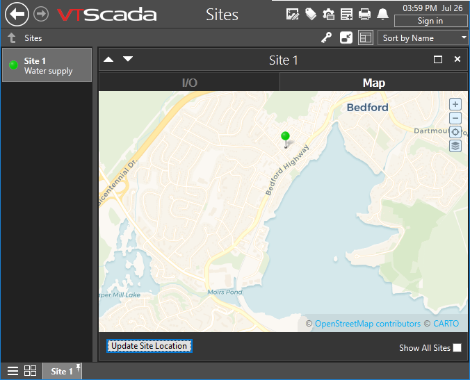
You may find it easier to set the location using the map interface than to enter the latitude and longitude values here. See: Site Map.
Latitude and Longitude
Holds location coordinates for this tag, thereby allowing it to be represented on a Site Map page.
Custom Details Page
If a custom details page has been created for this context tag, then that page should be selected here. If there is no custom details page, then operators will see the standard Site Details page upon clicking the pin for this tag in a Site Map.
Advanced Configuration:
The default page selection dialog has a filter for "all pages" or "site pages", meaning those that take a site tag as the first parameter.
You can add either of the following two properties in the Edit Properties page of the Application Configuration dialog to restrict this filter:
LimitPageListToSitesPages
System section. Set to 1 (TRUE) to prevent access to the "all pages" option in the page selection dialog for all users.
LimitPageListToSitesPagesIfRealmUser
System section. Set to 1 (TRUE) to prevent access to the "all pages" option in the page selection dialog if the user belongs to a security group.
Custom Map Icon
If a custom map icon widget has been defined, you can select it here. That icon will then be used instead of the standard pin when this tag is represented on a Site Map page. If there is no custom map icon, then the standard pin will be used.
Site List Display
Assuming that this tag has site properties, it will be included in the list of a Sites page. What will happen when an operator clicks on this tag in that list depends on the Site List display choice, and on whether any of this tag's children are I/O tags.
- Display as Site: A click will open the Site Details page as a pop-up.
- Display as Folder: A click will leave focus on the Sites page, but the list will now show the child tags of this site.
- Exclude: This tag should not be shown in the Sites page list.
Map Zoom Level
If Automatic is chosen (the default) then when a map is opened, showing only this site, it will zoom to level 15, which shows only the immediate surroundings. You may select any value between 18 (the closest possible level) and 2 (showing the entire globe).
Default zoom level.
Polling driver tags enable users to establish groups of PLCs or RTUs that will be polled together. The widgets for a Polling Driver tag enable users to display pertinent data about the RTU or PLC with which they are associated.
The following widgets are available to Polling Driver tags:
Enable Polling Checkbox Widget
