SDS Driver Tag
SDS stands for SCADA Data Solutions, the provider of an alternative cloud service to store, process and access data from Emerson® Zedi Smart-Alek® remote electronic flow meter devices. This data can be pulled into VTScada using the SDS Driver. Note that, because the SDS service is not managed by Trihedral Engineering Ltd., any questions regarding the configuration of Zedi Smart-Alek® devices to use the SDS service should be directed to SCADA Data Solutions.
When using the SDS Driver, VTScada must be able to reach the configured URL (typically https://service.scadadatasolutions.com) on the configured port (typically 443).
The ID tab of every tag includes the same common elements: Name, Area, Description, and Help ID.
Name:
Uniquely identifies each tag in the application. If the tag is a child of another, the parent names will be displayed in a separate area before the name field.
You may right-click on the tag's name to add or remove a conditional start expression.
Area
The area field is used to group similar tags together. By defining an area, you make it possible to:
- Filter for particular tag groups when searching in the tag browser.
- Link dial-out alarm rosters to Alarm tags having a particular area.
- Limit the number of tags loaded upon startup.
- Filter the alarm display to show only certain areas.
- Filter tag selection by area when building reports.
When working with Parent-Child tag structures, the area property of all child tags will automatically match the configured area of a parent. Naturally, you can change any tag's area as required. In the case of a child tag, the field background will turn yellow to indicate that you have applied an override. (Orange in the case of user-defined types. Refer to Configuration Field Colors).
To use the area field effectively, you might consider setting the same Area for each I/O driver and its related I/O tags to group all the tags representing the equipment processes installed at each I/O device. You might also consider naming the Area property for the physical location of the tag (i.e. a station or name of a landmark near the location of the I/O device). For serial port or Roster tags, you might configure the Area property according to the purpose of each tag, such as System or Communications.
You may define as many areas as you wish and you may leave the area blank for some tags (note that for Modem tags that are to be used with the Alarm Notification System, it is actually required that the area field be left blank).
To define a new area, type the name in the field. It will immediately be added. To use an existing area, use the drop-down list feature. Re-typing an existing area name is not recommended since a typo or misspelling will result in a second area being created.
There is no tool to remove an area name from VTScada since such a tool is unnecessary. An area definition will exist as long as any tag uses it and will stop existing when no tag uses it (following the next re-start).
Description
Tag names tend to be brief. The description field provides a way to give each tag a human-friendly note describing its purpose. While not mandatory, the description is highly recommended.
Tag descriptions are displayed in the tag browser, in the list of tags to be selected for a report and also on-screen when the operator holds the pointer over the tag’s widget. For installations that use the Alarm Notification System, the description will be spoken when identifying the tag that caused the alarm.
The description field will store up to 65,500 characters, but this will exceed the practical limits of what can be displayed on-screen.
This note is relevant only to those with a multilingual user interface:
When editing any textual parameter (description, area, engineering units...) always work in the phrase editor. Any changes made directly to the textual parameter will result in a new phrase being created rather than the existing phrase being changed.
In a unilingual application this makes no difference, but in a multilingual application it is regarded as poor practice.
Help Search Key
Used only by those who have created their own CHM-format context sensitive help files to accompany their application.
Server List
Select (or create) a named server list.
SDS Driver properties, Settings tab
The SDS Driver Settings tab governs the operation of the driver, service authentication, and device identification. To communicate with the SDS service, all parameters must be configured.
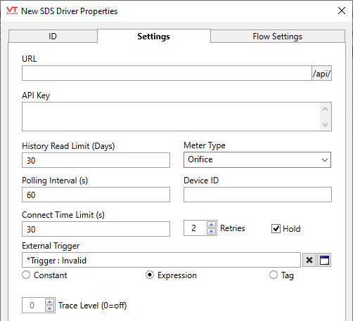
URL
The URL of the SDS service to query. Will typically be https://service.scadadatasolutions.com.
API Key
Authentication key used to access data in the cloud service. This key should be provided by SDS when registering your devices with the service.
History Read Limit (Days)
Maximum number of days in the past to read data for.
Meter Type
The type of Zedi Smart-Alek® meter. May be "Orifice" or "E-Tube". The type of meter informs the calculations done on data in processed data requests (GetProcessedData and GetPeriodicData API calls).
Device ID
The identifier of the device whose data is being read. Like the API key, this should be supplied by SDS.
Polling Interval (s)
How often, in seconds, to poll the SDS service.
The SDS driver will poll all data at this configured rate, and will not obey scan intervals configured in I/O tags.
Connect Time Limit (s)
The length of time, in seconds, that the driver should wait for a reply from the device.
Retries
The number of times to retry a message before declaring an error.
Use only if the driver is connected to a device that uses a serial port or a UDP/IP port that is configured to be polled. When connected directly to a device using TCP/IP, this value should normally be set to 0 since TCP/IP is a guaranteed message delivery protocol.
For unreliable communications, such as radio, set to 3 or 4.
Hold
Select this to have I/O tags attached to the driver hold their last value in the event of a communication failure. If not selected, tags will have their value set to invalid on a communication failure.
External Trigger
An additional, optional trigger to start reads.
Trace Level
Controls debug logging. A value of 0 (default) disables debug logging, while a value of 3 sets the logging level to high. Logs are recorded to the application "Data/TraceFiles" folder.
SDS Driver Properties, Flow Settings tab
It is expected that in many applications, the SDS driver will be used with a Flow Computer. If so, the Flow Computer tag selected here will disable the remaining flow setting parameters.
Otherwise, use this tab to enter a static set of flow settings to be used for processed data reads (GetProcessedData and GetPeriodicData API calls).
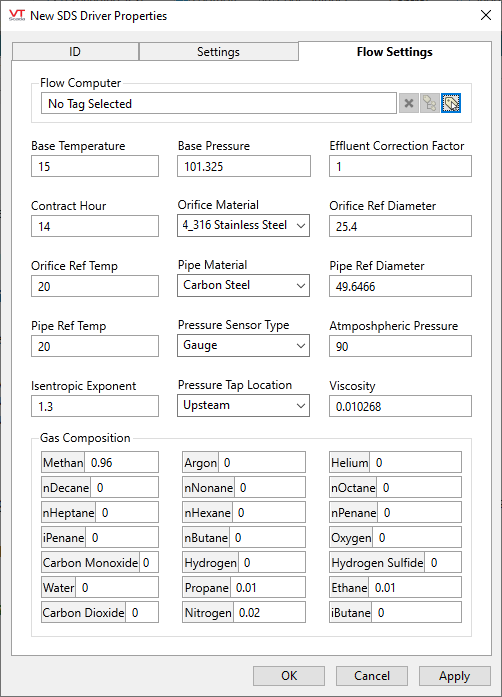
Flow Computer
The linked Flow Computer. When used with a Flow Computer, the flow settings are managed from the Flow Computer page's Configuration tab.
Base Temperature
Baseline temperature of the meter.
Base Pressure
Baseline pressure of the meter
Effluent Correction Factor
Correction factor for effluent.
Contract Hour
Contract hour used for daily history reads.
Orifice Material
Material of the orifice. Options are: 304_316 Stainless Steel, 304 Stainless Steel, 316 Stainless Steel, Monel, and Carbon Steel.
Orifice Ref Diameter
Reference diameter of the orifice.
Orifice Ref Temp
Reference temperature the orifice.
Pipe Material
Material of the pipe. Options are: 304_316 Stainless Steel, 304 Stainless Steel, 316 Stainless Steel, Monel, and Carbon Steel.
Pipe Ref Diameter
Reference diameter of the pipe.
Pipe Ref Temp
Reference temperature the pipe.
Pressure Sensor Type
Type of pressure sensor. Options are Gauge and Absolute.
Atmospheric Pressure
Atmospheric pressure at the meter.
Isentropic Exponent
Isentropic exponent at the meter.
Pressure Tap Location
Location of the tap in relation to the orifice. Options are Upstream or Downstream.
Viscosity
Viscosity of the contents of the pipe.
Gas Composition
Composition of gasses in the pipe, expressed in mole fractions. Note that the gas composition components must sum to 1.
The following widgets are available to display information about your SDS Driver tags:
