Grundfos Dedicated Controls
A single Grundfos Dedicated Controls tag includes all of the I/O required to monitor and operate a Grundfos CU 36X series pumping station. (https://www.grundfos.com/)
These create several child tags that do count towards you license limit, but as containers, are not themselves counted.
The controller calculates daily statistics and can provide timestamp information in the form of custom data logs and an event log. Due to the method used for calculation of statistics, local time is needed on the controller therefore the controller includes a time zone parameter.
By default, the controller is set to AutoAcknowledge mode. This is done so that when switching between operating modes (such as interlock and auto) that the operator does not need to click Cancel before reentering a mode.
The controller checks whether the station is controlled by float switches or a level sensor. If more than 2 floats are installed, then the system is float switch controlled and the setpoints tab is not needed.
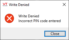
If the controller requires a PIN code and an incorrect code is given, no write will occur. Direct write calls will still work, so that the pin code can be sent via the custom widget. Note that this widget is included in the automatically-built station page only if the Write Lock Enabled option is selected on the Settings tab.
Grundfos Dedicated Controls Event Log
The ID tab of every tag includes the same common elements: Name, Area, Description, and Help ID.
Name:
Uniquely identifies each tag in the application. If the tag is a child of another, the parent names will be displayed in a separate area before the name field.
You may right-click on the tag's name to add or remove a conditional start expression.
Area
The area field is used to group similar tags together. By defining an area, you make it possible to:
- Filter for particular tag groups when searching in the tag browser.
- Link dial-out alarm rosters to Alarm tags having a particular area.
- Limit the number of tags loaded upon startup.
- Filter the alarm display to show only certain areas.
- Filter tag selection by area when building reports.
When working with Parent-Child tag structures, the area property of all child tags will automatically match the configured area of a parent. Naturally, you can change any tag's area as required. In the case of a child tag, the field background will turn yellow to indicate that you have applied an override. (Orange in the case of user-defined types. Refer to Configuration Field Colors).
To use the area field effectively, you might consider setting the same Area for each I/O driver and its related I/O tags to group all the tags representing the equipment processes installed at each I/O device. You might also consider naming the Area property for the physical location of the tag (i.e. a station or name of a landmark near the location of the I/O device). For serial port or Roster tags, you might configure the Area property according to the purpose of each tag, such as System or Communications.
You may define as many areas as you wish and you may leave the area blank for some tags (note that for Modem tags that are to be used with the Alarm Notification System, it is actually required that the area field be left blank).
To define a new area, type the name in the field. It will immediately be added. To use an existing area, use the drop-down list feature. Re-typing an existing area name is not recommended since a typo or misspelling will result in a second area being created.
There is no tool to remove an area name from VTScada since such a tool is unnecessary. An area definition will exist as long as any tag uses it and will stop existing when no tag uses it (following the next re-start).
Description
Tag names tend to be brief. The description field provides a way to give each tag a human-friendly note describing its purpose. While not mandatory, the description is highly recommended.
Tag descriptions are displayed in the tag browser, in the list of tags to be selected for a report and also on-screen when the operator holds the pointer over the tag’s widget. For installations that use the Alarm Notification System, the description will be spoken when identifying the tag that caused the alarm.
The description field will store up to 65,500 characters, but this will exceed the practical limits of what can be displayed on-screen.
This note is relevant only to those with a multilingual user interface:
When editing any textual parameter (description, area, engineering units...) always work in the phrase editor. Any changes made directly to the textual parameter will result in a new phrase being created rather than the existing phrase being changed.
In a unilingual application this makes no difference, but in a multilingual application it is regarded as poor practice.
Help Search Key
Used only by those who have created their own CHM-format context sensitive help files to accompany their application.
Grundfos Dedicated Controls tag: Settings tab
Take note of the well depth that is uploaded from the RTU. If it is significantly larger than the normal operating range, you must adjust your I/O deadbands accordingly.
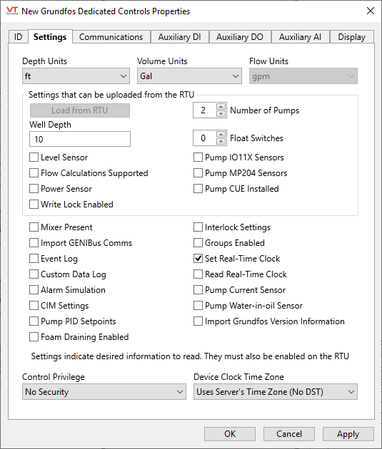
Depth Units / Volume Units / Flow Units
Select the system of measurement (US or SI) for each.
The following block of settings can be uploaded from the RTU
Load From RTU
Command button, enabled only if connected to a valid RTU.
Number of Pumps
Child tags are enabled to support the defined number. Should be set manually to avoid the chance of an incorrect number due to a poor communication link.
Well Depth
Ensure that the number matches the depth units specified at the top of the dialog. The value can be verified from register 00303.
Float Switches
Child tags are enabled to support the defined number. Will be set automatically using register 00217 when read from the RTU, or you can use the control here to set the number manually.
Level Sensor
Indicates the presence of a level sensor. Will be set automatically using a presence bit, or you can override that value manually.
Pump I011X Sensors
If an IO11X is found attached to pumps, it is enabled to import additional I/O from the add-on. May be enabled manually.
Flow Calculations Supported
Will be enabled during a scan if the unit has a dedicated flow sensor. Can also be enabled manually if internal flow calculations are performed.
Pump MP204 Sensors
Will be enabled if an MP204 is detected during a scan, thereby enabling its I/O point reading. Can also be enabled manually.
Power Sensor
Will be enabled if a power sensor is detected on the RTU. Can also be enabled manually.
Pump CUE Installed
Will be enabled if a Grundfos CUE (variable speed drive) is detected on the RTU. Can also be enabled manually.
Write Lock Enabled
Check boxes, indicating the presence of each attribute on the RTU that can be enabled or disabled via an RTU scan.
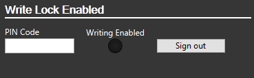
Use the following settings to indicate information that you want to read. You must also enable each of these attributes on the RTU. For this set, you must check each option - none can be read from the RTU.
Mixer Present
Enable to read in mixer information, if present.
Interlock Settings
Enable to adjust interlock settings, if used.
Import GENIBus Comms
Enable to view GENIbus communications for detecting problems between the controller and the pumps.
Groups Enabled
Enable in order to edit pump group settings, if used.
Event Log
Enable in order to read the event log from the device. Required if using the Grundfos Dedicated Controls Event Log tag.
Set Real-Time Clock
Enable to allow VTScada to set the real time clock automatically based on the selected time zone.
Custom Data Log
Enable to allow reading of the custom data logs. Note that these cannot be configured from VTScada. Required if using the Grundfos Dedicated Controls Custom Data Log tag.
Read Real-Time-Clock
Enable to display the current time of the real-time clock on the RTU.
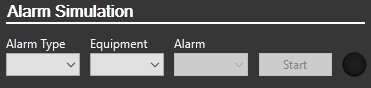
Alarm Simulation
Enable to use the alarm simulation tool in the controller. This will be added to the Station tab of the automatically-generated station page.
Pump Current Sensor
Enable if a current sensor is installed on the pump that is not part of an IO11X add-on.
CIM Settings
Enable to view and edit the CIM card settings (Communication Interface Module). Needed only for configuration.
Pump Water in Oil Sensor
Enable if an oil-in-water sensor is on the pump that is not part of an IO11X or MP204 module.
Pump PID Setpoints
Enable to allow modification of the pump PID setpoints.
Import Grundfos Version Information
Enable to display Grundfos-specific information on the inputs tab.
Foam Draining Enabled
Select in order to gain access to the setpoint value if the foam-draining feature of the controller is enabled.
Control Privilege
Select a custom security privilege
Device Clock Time Zone
The default is to use the server's time zone, without adjusting for daylight savings time. Instead, you may choose to use the device clock in UTC, or any standard time zone.
Grundfos Dedicated Controls tag: Communications tab
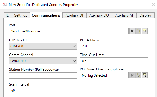
Port
Select the TCP/IP or Serial Port tag that is to be used for communication with the equipment. The ancestor port is selected automatically if this tag is created as a child of a port. If there is a sibling port and no ancestor port, then the sibling port will be selected automatically.
CIM Model
Choose between models CIM 200, CIM 250 GSM, CIM 250 GPRS, or CIM 500
PLC Address
The standard port is 231, but may be overridden if necessary.
Comm Channel
Serial RTU, Open Modbus TCP/IP or Open Modbus TCP
Time-Out Limit
Set the receiver time-out limit in seconds or fractions of a second. This is the length of time that this driver should wait for a reply from the PLC or RTU.
Station Number (Poll Sequence)
Used by the built-in Polling Driver Tags. Use the Poll Sequence Number field to specify a number that identifies this polling driver's place in the polling sequence for the identified poll group.
For example, if you have 5 polling drivers, each of which is associated with a different communication driver (e.g. Modbus1, Modbus2, etc.), and all 5 polling drivers have the same poll group identified (in their Poll Group Name property), you must enter a number from 1 to 5 for each of the polling drivers to determine the order in which the 5 communication drivers belonging to the poll group will be polled.
I/O Driver Override (optional)
Typically uses a built-in Modbus Compatible Device Driver, but you may use this tool to select another.
Scan Interval
Used by the built-in Polling Driver. The amount of time (in seconds) between requests for data from this Polling Driver tag to the I/O device with which it is associated.
Grundfos Dedicated Controls tag: Auxiliary DI tab
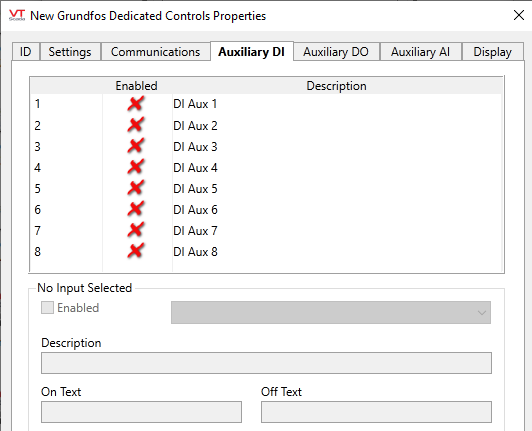
Table of auxiliary digital inputs.
Configuration tools affect only the selected entry in the table. If no entry is selected, no controls are enabled.
Enabled
Controls whether the selected input is enabled.
No other configuration is possible if the input is not enabled.
Custom
The appearance of this parameter as a drop-down matches those on the following tabs, but there is no option other than "Custom".
Description
Use to override the default description of the input.
On Text / Off Text
Displayed by certain widgets when the input is in state 1 (On) or state 0 (Off)
Grundfos Dedicated Controls tag: Auxiliary DO tab
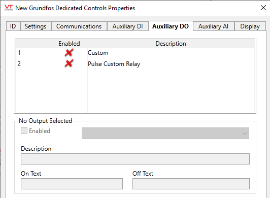
Table of auxiliary digital outputs. Select an entry in the table in order to enable the following configuration controls:
Enabled
Controls whether the selected output is enabled.
No other configuration is possible if the output is not enabled.
Custom option
Select between "Custom" and "Pulse Custom Relay".
Description
Use to override the default description of the output.
On Text / Off Text
Define the text to be displayed by widgets that support this feature.
Grundfos Dedicated Controls tag: Auxiliary AI tab
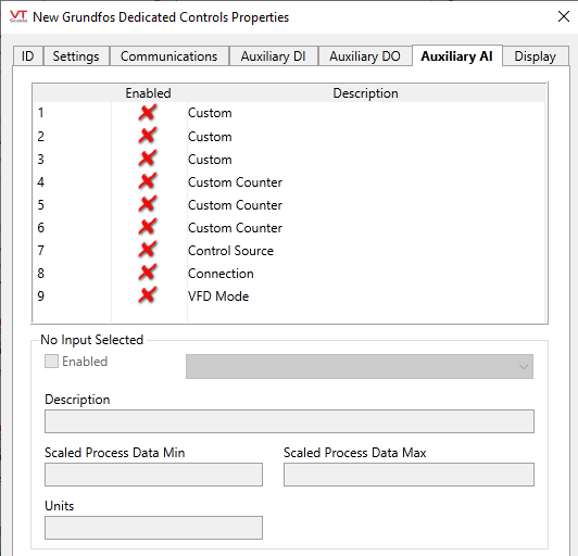
Table of auxiliary analog inputs. Select an entry in the table in order to enable the following configuration controls:
Enabled
Controls whether the selected output is enabled.
No other configuration is possible if the output is not enabled.
Custom option
Choose between "Custom", "Custom Counter", "Control Source", "Connection" or "VFD Mode"
Description
Use to override the default description of the input.
Scaled Process Data Min and Max
Defines the scaling from raw data (defined by the controller) to the displayed engineering units.
Units
Engineering units, informing the operator what the value represents.
Grundfos Dedicated Controls tag: Display tab
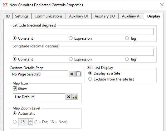
Latitude and Longitude
Holds location coordinates for this tag, thereby allowing it to be represented on a Site Map page.
Custom Details Page
If a custom details page has been created for this context tag, then that page should be selected here. If there is no custom details page, then operators will see the standard Site Details page upon clicking the pin for this tag in a Site Map.
Map Icon
If a custom map icon widget has been defined, you can select it here. That icon will then be used instead of the standard pin when this tag is represented on a Site Map page. If there is no custom map icon, then the standard pin will be used.
Site List Display
Assuming that this tag has site properties, it will be included in the list of a Sites page. What will happen when an operator clicks on this tag in that list depends on the Site List display choice, and on whether any of this tag's children are I/O tags.
- Display as Site: A click will open the Site Details page as a pop-up.
- Display as Folder: A click will leave focus on the Sites page, but the list will now show the child tags of this site.
- Exclude: This tag should not be shown in the Sites page list.
Map Zoom Level
If Automatic is chosen (the default) then when a map is opened, showing only this site, it will zoom to level 15, which shows only the immediate surroundings. You may select any value between 18 (the closest possible level) and 2 (showing the entire globe).
The following widgets are supported in addition to those built into the custom Grundfos CU36X pages.
(It would be unusual to draw any of the component widgets on its own, therefore they are not described here.)
| Alarm Priority Box | Alarm Priority Icon |
| Alarm List | Site Icon Widget |
| Site Summary Widget | Site Alarm List |
| Tag List Widget | Draw HDV Widget |
