UDP/IP Port Tags
Not counted towards your tag license limit.
In the unusual event that you have multiple devices attempting to use the same channel at the same time across multiple ports, you might consider adding Comm Link Sequencer Tags to serialize requests.
Monitor drivers, not ports. A port tag has a value only on the server that is communicating with hardware and will be blank on all other servers. The value of a port tag is not synchronized across all workstations. (Unlike I/O and driver tags.) If the alarm server and I/O servers are different machines, an alarm on a port tag will not activate. Do not attach an alarm to any port tag.
A port tag widget drawn on a page represents only state of the port on the local machine.
Warnings:
All UDP/IP port tags use an internal listener port to receive datagram responses. The is what the Local Port Number defines (it is also used as the transmit port number).
The engine will automatically route responses back to the UDP socket stream if the remote IP address matches that of the stream. This means that multiple UDP/IP port tags can make use of the same local port number (internally they share the UDP port listener). This UDP port listener requires that the port be free, thus any conflict for use of the port runs the risk of disrupting UDP/IP communications.
Take note of the following possible errors. Some may not cause problems until the next re-start of the application.
1) UDP/IP Port and IP Network Listener tag sharing the same port number.
The IP Network Listener tag uses a socket server to function. This can interfere with the UDP listener port used by the UDP/IP port tag. The VTScada engine will already listen for UDP/IP datagram packets and place them into existing UDP streams if the remote IP address matches that of the UDP stream.
In general, do not configure an IP Network Listener tag with a UDP port unless you are certain that one is required. If you are certain, then ensure that they do not share the same port number. See also, warnings 2 and 3.
2) UDP/IP address left blank
The UDP/IP port tag functions as a socket server when the Name/Address field is invalid (blank) but a port number is configured. It will listen on the defined port number for any datagram messages and will bind to the first one received. In this way it is similar to an IP Network Listener, only without the discrimination/filtering abilities. Note that you can have only one listener in the system, whether that be a UDP port configured to listen or a IP Network Listener.
If you are unsure of the remote address then enter 0.0.0.0 rather than leaving the field blank.
3) Disconnect Delay defined.
> Do not define unless you are using an IP Network Listener in combination with the UDP/IP port.
> Do not use an IP Network Listener with a UDP/IP port unless you are certain that one is required.
This option was included exclusively for use with IP Network Listener tags. There is one situation where the engine-level UDP handling is insufficient, which is when the remote device can respond with different IP addresses over time. Use the Disconnect Delay to disassociate the remote IP after a period of inactively. The VTScada engine is then able to establish new remote IP address associations with the remote device via IP Network Listener tags. It is extremely unlikely that there would be a reason to use an IP Network Listener with a UDP port unless this is the case.
UDP and TCP/IP Error Codes
A valid TCP/IP (and UDP/IP) port tag can have any of the following values.
Error codes from the underlying operating system may be passed through. For codes not listed here, refer to https://learn.microsoft.com/en-us/windows/win32/debug/system-error-codes--9000-11999-
| Error code (Decimal) |
Error code (Hex) |
Meaning |
|---|---|---|
| 00 | 0x0 | No Error |
| 259 | 0x103 | Port did not connect |
| 260 | 0x104 | Connection was lost |
| -802 | Neither the Common Name (CN) or Subject Alternative Names (SAN) used in the X.509 certificate match the target device name. | |
| -803 | There is no Local Security Authority (LSA) context for the operation | |
| -804 | The clocks on the client and server machines are too far skewed. | |
| -10048 | Only one usage of each socket address (protocol/network address/port) is normally permitted. | |
| -10051 | Port unreachable | |
| -10053 | Connection aborted | |
| -10054 | Connection reset | |
| -10060 | Connection timeout | |
| -10061 | Connection refused | |
| -10065 | Host unreachable |
See also: Client Socket Error Codes
Comm Link Sequencer Tags - Serialize requests for the same communication channel across ports.
Ethernet to Serial Converters - Troubleshooting.
The ID tab of every tag includes the same common elements: Name, Area, Description, and Help ID.
Name:
Uniquely identifies each tag in the application. If the tag is a child of another, the parent names will be displayed in a separate area before the name field.
You may right-click on the tag's name to add or remove a conditional start expression.
Area
The area field is used to group similar tags together. By defining an area, you make it possible to:
- Filter for particular tag groups when searching in the tag browser.
- Link dial-out alarm rosters to Alarm tags having a particular area.
- Limit the number of tags loaded upon startup.
- Filter the alarm display to show only certain areas.
- Filter tag selection by area when building reports.
When working with Parent-Child tag structures, the area property of all child tags will automatically match the configured area of a parent. Naturally, you can change any tag's area as required. In the case of a child tag, the field background will turn yellow to indicate that you have applied an override. (Orange in the case of user-defined types. Refer to Configuration Field Colors).
To use the area field effectively, you might consider setting the same Area for each I/O driver and its related I/O tags to group all the tags representing the equipment processes installed at each I/O device. You might also consider naming the Area property for the physical location of the tag (i.e. a station or name of a landmark near the location of the I/O device). For serial port or Roster tags, you might configure the Area property according to the purpose of each tag, such as System or Communications.
You may define as many areas as you wish and you may leave the area blank for some tags (note that for Modem tags that are to be used with the Alarm Notification System, it is actually required that the area field be left blank).
To define a new area, type the name in the field. It will immediately be added. To use an existing area, use the drop-down list feature. Re-typing an existing area name is not recommended since a typo or misspelling will result in a second area being created.
There is no tool to remove an area name from VTScada since such a tool is unnecessary. An area definition will exist as long as any tag uses it and will stop existing when no tag uses it (following the next re-start).
Description
Tag names tend to be brief. The description field provides a way to give each tag a human-friendly note describing its purpose. While not mandatory, the description is highly recommended.
Tag descriptions are displayed in the tag browser, in the list of tags to be selected for a report and also on-screen when the operator holds the pointer over the tag’s widget. For installations that use the Alarm Notification System, the description will be spoken when identifying the tag that caused the alarm.
The description field will store up to 65,500 characters, but this will exceed the practical limits of what can be displayed on-screen.
This note is relevant only to those with a multilingual user interface:
When editing any textual parameter (description, area, engineering units...) always work in the phrase editor. Any changes made directly to the textual parameter will result in a new phrase being created rather than the existing phrase being changed.
In a unilingual application this makes no difference, but in a multilingual application it is regarded as poor practice.
Help Search Key
Used only by those who have created their own CHM-format context sensitive help files to accompany their application.
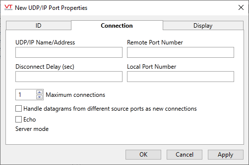
UDP/IP Port properties Connection tab
The Connection tab of the UDP/IP port tag properties folder contains properties that enable communications.
If the UDP/IP Name/Address field is blank, then behavior will depend on the configuration of the Remote Port Number and Local Port Number as follows:
Remote Port Number and Local Port Number configured:
The tag will be a listener on the port and any inbound datagrams will sit in a bi-directional stream (i.e. a driver can both read and write to the stream). Writes to the stream cause datagrams to be issued to the device that originated the inbound datagram that created the stream and are transmitted to the "Remote Port Number" on the device.
Remote Port Number blank and Local Port Number configured:
The tag will be a listener on the specified local port.
Remote Port Number blank and Local Port Number blank:
The tag will do nothing.
UDP/IP Name/Address
The UDP/IP Name/Address field provides a space for the name or IP address of the server to which this tag will connect. (For example, MyRTU.com, or 198.255.32.1). If using IPv6 addressing, names are strongly recommended over specific addresses.
If using a numeric address, do not include leading zeros. These are likely to be reinterpreted as octal values.
Remote Port Number
Specifies the port number on the host address through which communications are enabled.
Local Port Number
Sets the port number on which the local PC should listen.
Disconnect Delay
Do not configure unless you have determined that an IP Network Listener is required and you are absolutely certain that a disconnect is required due to the RTU using differing IP addresses.
Specify in seconds or fractions of a second, the amount of idle time that should pass before the connection to the server is terminated. To be used only when the IP address of the remote device changes between each transmission, thus allowing a new connection.
Handle datagrams from different source ports as new connections/Only accept datagrams from the configured remote port
The label of this checkbox is "Handle datagrams from different source ports as new connections" when in server mode and "Only accept datagrams from the configured remote port" when in client mode.
- VTScada sends messages from the local port to the remote destination port.
- The remote device sends from the remote source port to the local port.
- The remote destination port and remote source port are often the same port, but may not be. It is because of this difference that the following options are required.
If running in server mode (the UDP/IP Name/Address field is empty)
LABEL: "Handle datagrams from different source ports as new connections"
A UDP "stream" is initially created when the first datagram is received from the remote device. For subsequent datagrams:
- If the remote device sends a datagram from the same port as the previous one, the datagram will appear in the same stream as the first one. Leave the check box unselected.
- If the remote device sends a datagram from a different port as the previous one, then:
- Check box selected: A new stream is created into which the datagram will be placed.
- Check box NOT selected: The datagram is placed in the existing stream.
This has significance when the driver using the UDP port attempts to transmit using the existing stream. When the check box is selected, the stream is associated with a specific port on the remote device and will be sent there. When the check box is NOT selected, it will be sent to the port on the remote device that issued the datagram that created the stream.
If running in client mode (the UDP/IP Name/Address field is configured)
LABEL: "Only accept datagrams from the configured remote port"
A UDP "stream" is initially created when the driver requests it. For all datagrams:
- If the remote device sends a datagram from the port matching the Remote Port Number in this driver, then the datagram will appear in the stream.
- If the remote device sends a datagram from a different port then:
- Checkbox selected: If there is no existing UDP tag that matches the remote port number the datagram is discarded.
- Checkbox NOT selected: The datagram is placed in the existing stream.
With the check box selected, drivers that care about the remote port from which the datagram has been sent can utilize multiple UDP tags and have inbound datagrams from (for example) a pair of remote port numbers, stored in separate streams.
If you have more than one UDP/IP tag with the checkbox selected and with the same address and local port, the socket connection could fail and show "10048 error".
Under these conditions, regardless of the remote port numbers, more than one tag would appear to be an eligible recipient of the datagram, creating a conflict.
Maximum Connections
Set the maximum number of concurrent connection between VTScada and the address configured in this tab. For any benefit to be seen, both the driver and the PLC must support multiple concurrent connections. If the tag is running in server mode or the local port is not given, the maximum connections will be limited to 1.
On the VTScada side, the following drivers support this feature:
- TI505 Device Driver
- Delta Driver
- Enron Modbus Driver
- Mitsubishi Driver
- Modbus Compatible Device Driver
- Toyopuc Driver
Echo
Select whether the transmitted data should be echoed in the received data.
If the Echo check box is selected, the driver should expect that the transmitted data will be echoed in the received data.
By default, the Echo check box is not selected.
When this tag is represented on screen by widgets that can use a Style Settings tag, you can save development time by choosing the Style Settings tag that holds the correct display configuration for this tag instance.
The default configuration will use System Style, the default style tag that is automatically part of every new VTScada application. If a Style Settings tag is an ancestor or else a sibling, it will become the new automatic default.

The following widgets are available to display information about your application’s UDP/IP Port tags:
