Rockwell Driver Tag
Not counted towards your tag license limit.
As of VTScada version 12.1, this tag replaces the legacy CIP/ENIP Driver (Control and Information Protocol) and combines support for multiple Rockwell devices into one driver.
The Rockwell driver type provides an interface between VTScada and Rockwell PLCs that use the CIP, CSP Socket or Serial communication protocols. This includes: CompactLogix, ControlLogix, Micro 800 series, PLC-5, SLC-500 and MicroLogix 1100-1500 PLCs.
Driver Errors: To learn more about the cause of an error condition, refer to the Driver Summary Report and the Driver Error Report, both of which are available in the Reports page. The Show Stats button will also provide current and last error messages: Show Statistics Button Widget
The Rockwell driver is able to query the PLC's Tag configuration on the CompactLogix series of PLCs. Therefore, those configurations will support the Import function to create tags in your application automatically. Before attempting the import, ensure that:
- You are connected to the correct Rockwell device.
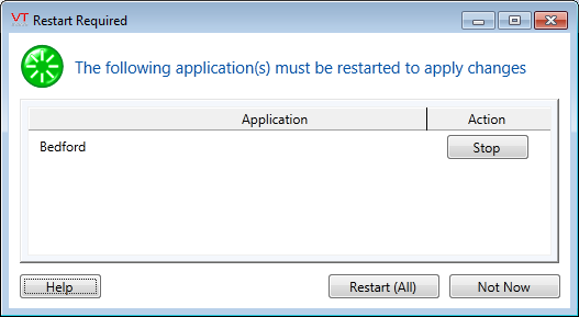
- Your application is not pending a restart.
- Your account has the Tag Modify privilege.
Instructions and error descriptions are provided in the documentation under Import Tags from PLCs. Note that only ControlLogix modes support PLC tag upload.
The Rockwell driver may have trouble doing a 'large' PLC upload in a certain configuration. In this case, a 'large' PLC tag upload is defined as one that takes longer than the 'CIP Connection Timeout' parameter.
Some tags displayed in the Address Assist dialog may return a "Path Destination Unknown" error, depending on the PLC's ExternalAccess attribute.
CIPForwardCloseAdvance - Default: .5 Used to compensate for network latency to avoid the situation of Forward Close commands reaching the destination after the connection has already been closed in the PLC.
CIPTransTimeOutCount - Defines the number of transaction timeouts for a CIP driver before the connection is dropped.
CIPMaxNumberofSessions - Deprecated.
RockwellDriverDHRIOChannels - Default: 2. Number of DH+ channels that can be addressed in a 1756-DHRIO card.
RockwellDriverMaxCPInstance -Default: 1. The maximum Connection Point instance number to use.
RockwellPollB4BuildComplete - Default: 0. Set to 1 to poll before all reads are built.
RockwellReadsBeforeAddressError - Default: 2. The number of reads before setting an address error. Set to zero to disable the Address Error dialog in the Symbolic addressing mode.
RockwellWriteMode - Default 0. Set to 1 for Fragmented (0x53) or 2 for Tag (0x4D).
RockwellMaxUploadIdle - Default 15. The maximum idle time in seconds for the tag upload procedure during tag importing.
RockwellDriverMaxInboundPacketSize - Sets the maximum inbound packet size for your Rockwell drivers.
RockwellDriverMaxOutboundPacketSize - Sets the maximum outbound packet size for your Rockwell drivers.
RockwellDriverMaxStringLength - Sets the maximum string length for your Rockwell drivers.
The ID tab of every tag includes the same common elements: Name, Area, Description, and Help ID.
Name:
Uniquely identifies each tag in the application. If the tag is a child of another, the parent names will be displayed in a separate area before the name field.
You may right-click on the tag's name to add or remove a conditional start expression.
Area
The area field is used to group similar tags together. By defining an area, you make it possible to:
- Filter for particular tag groups when searching in the tag browser.
- Link dial-out alarm rosters to Alarm tags having a particular area.
- Limit the number of tags loaded upon startup.
- Filter the alarm display to show only certain areas.
- Filter tag selection by area when building reports.
When working with Parent-Child tag structures, the area property of all child tags will automatically match the configured area of a parent. Naturally, you can change any tag's area as required. In the case of a child tag, the field background will turn yellow to indicate that you have applied an override. (Orange in the case of user-defined types. Refer to Configuration Field Colors).
To use the area field effectively, you might consider setting the same Area for each I/O driver and its related I/O tags to group all the tags representing the equipment processes installed at each I/O device. You might also consider naming the Area property for the physical location of the tag (i.e. a station or name of a landmark near the location of the I/O device). For serial port or Roster tags, you might configure the Area property according to the purpose of each tag, such as System or Communications.
You may define as many areas as you wish and you may leave the area blank for some tags (note that for Modem tags that are to be used with the Alarm Notification System, it is actually required that the area field be left blank).
To define a new area, type the name in the field. It will immediately be added. To use an existing area, use the drop-down list feature. Re-typing an existing area name is not recommended since a typo or misspelling will result in a second area being created.
There is no tool to remove an area name from VTScada since such a tool is unnecessary. An area definition will exist as long as any tag uses it and will stop existing when no tag uses it (following the next re-start).
Description
Tag names tend to be brief. The description field provides a way to give each tag a human-friendly note describing its purpose. While not mandatory, the description is highly recommended.
Tag descriptions are displayed in the tag browser, in the list of tags to be selected for a report and also on-screen when the operator holds the pointer over the tag’s widget. For installations that use the Alarm Notification System, the description will be spoken when identifying the tag that caused the alarm.
The description field will store up to 65,500 characters, but this will exceed the practical limits of what can be displayed on-screen.
This note is relevant only to those with a multilingual user interface:
When editing any textual parameter (description, area, engineering units...) always work in the phrase editor. Any changes made directly to the textual parameter will result in a new phrase being created rather than the existing phrase being changed.
In a unilingual application this makes no difference, but in a multilingual application it is regarded as poor practice.
Help Search Key
Used only by those who have created their own CHM-format context sensitive help files to accompany their application.
Server List
Select (or create) a named server list.
Rockwell Driver properties - Configuration tab
The Rockwell driver may have trouble doing a 'large' PLC upload in a certain configuration. In this case, a 'large' PLC tag upload is defined as one that takes longer than the 'CIP Connection Timeout' parameter.
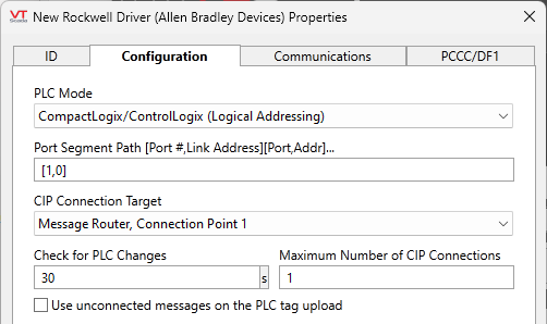
PLC Mode
Choices include:
- CompactLogix/ControlLogix (Logical Addressing - Default)
- CompactLogix/ControlLogix (Instance Symbolic Addressing)
- CompactLogix/ControlLogix (Symbolic Addressing)
For CompactLogix and ControlLogix PLCs, there are three choices. The Logical Addressing mode is the most efficient and fastest read method but requires an upload of the PLC tag information. This mode also requires the building of 'Readblocks' within the PLC each time there is a new CIP connection to the device.
The Instance Symbolic Addressing mode is the second-most efficient read method and also requires an upload of the PLC tag information. However, this mode does not require the building of 'Readblocks' so it will be quicker to recover from a CIP Connection loss.
The Symbolic Addressing mode is the least efficient read method but does not require an upload of PLC tag information nor the building of 'Readblocks'. This mode is best used on smaller PLCs with slower communication links or slow period polling requirements (i.e. > 15-30 minutes).
- Micro820/850 (Symbolic Addressing)
For Micro 800 series PLCs, Symbolic Addressing is the only read method available. (There is no PLC tag upload, nor the building of Readblocks).
The Address Select tool is always available when configuring your I/O tags when using the Logical Addressing or the Instance Symbolic Modes. In the Symbolic mode, the Address Select is available but 'optional', so the PLC tag Read must be triggered from Address Select dialog as it is not automatically uploaded in this mode. The Address Select is not available in the Micro 800 series PLCs.
Select to connect to older Allen Bradley PLCs that support the PCCC protocol (Data File addressing encoded in CIP messages), such as PLC-5 (Enhanced controllers only), SLC-5/05 and MicroLogix 1100-1500, selected through the PLC Type control, in the PCCC/DF1 tab.
Recommended only when the target PLC supports EtherNet/IP connections directly (MicroLogix). While this mode also allows the routing through DHRIO cards, the Routed DH+ mode is more efficient and compatible with a broader range of controllers.
This mode is similar to the PCCC Mode in that it also supports Data File addressing-compatible PLCs (PLC-5, SLC-500 series and MicroLogix 1100-1500), but instead using Serial or CSP Sockets over TCP/IP. All protocol settings for this mode are set in the PCCC/DF1 tab. PLC-2, PLC-3 and PLC5-250 are not supported by the Rockwell driver. Use the Allen Bradley Driver with those controllers.
Used to reach PLCs connected to the DH+ channels of a 1756-DHRIO Interface Module, typically from a ControlLogix chassis, or an equivalent adapter, such as the ProSoft AN-X4-AB-DHRIO.
Like PCCC and Legacy modes, it is intended to communicate with older controllers, namely PLC-5 and SLC-500 series (Data File addressing), by encapsulating DF1 messages in CIP packets sent through CIP connections to the DHRIO card. Therefore, Port Segment Path must be targeted at the DHRIO card itself, rather than the PLC (do not add the segment containing the DH+ channel and station address to the Port Segment Path).
The DH+ channel (A or B) is selected on the CIP Connection Target drop-list, whereas the PLC Type and Address are configured in the PCCC/DF1 tab.
The ProSoft AN-X4-AB-DHRIO implements a virtual 4-slot rack with a single DH+ channel and a 1756-DHRIO card in slot 1. Therefore, the Port Segment Path must be set to [1,1] and CIP Connection Target to Channel A.
You may achieve improved response time when using the Rockwell's Symbolic Addressing modes from the driver by increasing the system overhead time slice setting within the PLC from 20% to 70% via the Logix 5000 or Studio 5000 software.
Use this information with caution, taking your unique situation into account. It may be less relevant for newer systems.
Port Segment Path [Port #, Link Address][Port,Addr]…
The Port Segment Path format is [Port ID, Link Address], and describes the path or route to access the data.
The Port ID is a number that describes the port by which the message will exit the communications card that received it.
- Port ID 0 is reserved.
- Port ID 1 is the backplane from a communications card
- Port ID 2 and 3 are the communication port of the communications cards.
For example port 2 on a DHRIO type card is DH+ channel A, while port 3 is channel B (PCCC mode only).
The Link Address is the destination address of the message for this pair of the port segment path. You may provide an IP address for Ethernet network, slot number for a backplane, (decimal) node number for DH+ and ControlNet networks and station address for DF1 networks. Note that node numbers in Routed DH+ mode must be set in the PCCC/DF1 tab, rather than in the Port Segment Path.
For example when accessing the CPU with a built-in Ethernet port, the Port ID would be 1 for the backplane and the link address would be the slot number of the CPU. If the CPU is in slot number 0 the Port Segment Path parameter should be set to [1,0].
In newer CIP devices such as the 1756-L83E processor, use an empty path rather than [1,0].
Further examples:
[1,5]
The message destination is slot number 5 of the backplane.
[1,5][2,18]
The message will be directed to slot number 5 on the backplane and then out port 2 of the communications card to node or station address 18, depending on the type of network
[1,5][2,10.158.2.20][1,0]
The message will be directed to slot number 5 on the backplane, then out port 2 of the Ethernet card to IP address 10.158.2.20 and then to slot number 0 of that backplane.
You must be familiar with the hardware to which you are connecting to correctly establish the Port Segment Path. The newer ControlLogix L80 series of PLCs can use a blank or a [] Port Segment path for connections directly to the processor.
CIP Connection Target
(Was: Path uses a Connection point) Select between Message Router, no Connection Point or Message Router, Connection Point 1
For native CIP modes (including PCCC in "Connected Mode"), this determines whether the connection target is the Message Router itself, or one of its 'connection points' (currently, the only option is instance #1). Defaults to "Message Router, Connection Point 1". The connection point is not needed when you are routing ‘through’ one device to another device, or when you are connecting to a ControlLogix L80 series processor via a separate IP card.
For Routed DH+ mode, it is used to select the DH+ Channel of the DHRIO card (A or B). Defaults to "DH+ Interface, Channel A".
If seeing the error, "789 (0x315) – FO: Invalid segment in connection path", set the connection target to "Message Router, no Connection Point.
Check for PLC Changes (s)
The Rockwell driver reads the entire PLC tag configuration into memory as dictated by the PLC Mode setting above. For the modes that require the PLC tag information, this parameter controls how often the PLC is checked to see if that tag configuration has changed from the last time it was uploaded. If a change is detected, the PLC tag configuration is reloaded.
In the Symbol addressing mode, where the PLC tag upload is optional, this parameter controls how that uploaded data (for use in the Address Assist dialog) is valid.
This parameter is ignored for the Micro 800 series and Data File addressing modes (PLC tag upload is not supported).
The full read of the PLC tags configuration can take time and will interrupt the driver's read process. This check time can be extended from the default of 30 seconds if:
- You are confident that the PLC tag configuration is not changing.
- You don't mind manually initiating the PLC tag upload when need to pick-up a new tag name/address from the PLC (if you have set this extremely large). This avoids the disruption that a PLC tag upload may cause.
Use unconnected messages on the PLC tag upload
Newer versions of Rockwell firmware support the use of unconnected messages when doing the PLC tag upload. This can significantly decrease the time it takes to do that upload.
You should perform a manual PLC tag upload (triggered from an Address Assist dialog) and watch via the Show Stats dialog, to see if this setting is faster for your configuration. Defaults to not using connected messages.
When PCCC over CIP is selected, this parameter becomes 'Use unconnected messages on all PCCC communication'. Enable 'unconnected messages' if the target PLC does not support CIP connections. The Rockwell driver will generate a "Service not supported" error if so.
Maximum Number of CIP Connections
Rockwell's implementation of the CIP protocol supports multiple CIP messages ‘in flight’ by opening multiple CIP Connections on a single EtherNet/IP Connection / TCPIP Socket. If you have enough PLC resources, communication bandwidth and host machine CPU capacity, then multiple CIP Connections will increase your system performance.
This parameter should be tuned for your specific configuration:
Increase the number of connections until all connections are not being used. The number of CIP Connections in use is shown in the driver's Show Stats dialog.
Decrease the number connections if either of the following occurs, usually on startup (as shown in the Show Stats dialog):
- CIP Connections start to fail to open with an insufficient Memory Buffer error
- CIP Connections start to fail with a timeout error
Up to 128 simultaneous CIP connections are supported, but 5 to 10 typically provide the best performance.
Default: 1 connection.
Rockwell Driver properties - Communications tab
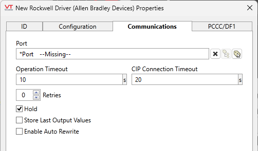
Port
Select the TCP/IP tag that will provide the IP address and port to be used when communicating with the PLC. Rockwell's default TCP/IP port number is 44818.
If using the Legacy mode, you may need a Serial or UDP port. Either can be used, but this means that it is also possible to use the traditional (the first 4 Rockwell Driver modes) CIP communication modes over a serial link instead of TCP/IP. This is not recommended because serial links would be too slow for CIP communication and should only be used in exceptional cases.
The Rockwell driver supports a shared serial port, which is needed for radio or modem-based communication. It is best configured with a Serial Port tag as the parent and Rockwell drivers as child tags of that port.
Shared port tags might be required in two situations:
- In Legacy Serial mode, a shared port is needed for radio or modem-based communication. It is best configured with a Serial Port tag as the parent and Rockwell drivers as child tags of that port.
- When accessing multiple PLCs through the same Ethernet interface card, (a common scenario in the Routed DH+ mode), it is possible to use either a single TCP/IP Port tag for all drivers, or one TCP/IP Port tag for each driver or group of drivers. Each Port tag will make exactly one TCP connection to the Ethernet card, therefore the Port tag's Maximum connections setting shall be left at the default setting of 1. Using multiple TCP/IP Port tags may improve the performance when communicating with tens of PLCs with such setting, but care should be taken not to exceed the maximum number of simultaneous TCP connections supported by the card.
Operation Timeout
Use to specify the time (in seconds) after which the driver will abort a communication attempt and declare a timeout error. The default value for Operation Timeout property is 10 (seconds). The Operation timeout x Retries should be less than the CIP Connection Timeout.
CIP Connection Timeout
The CIP Connection timeout is the time a CIP Messaging Connection remains open without any communication activity with the PLC. On hardwired or direct communication networks, which usually have faster tag poll times, the CIP Connection Timeout should be set higher than the poll rate so that the CIP Connections do not close between polls. This avoids the overhead of the Logical Address mode's PLC Readblock build, caused by the termination of a CIP Connection.
On bandwidth-limited networks (typically cellular or radio based), which usually have slower tag poll times, the CIP Connection Timeout should be lower than the poll rate so that the CIP Connection closes after the poll completes. In this mode of operation, the driver should be run in the Symbolic Addressing mode to avoid the overhead of the Logical Address mode's Readblock build.
In order to determine which mode of operation is best for your configuration, you should perform a detailed analysis of the factors such as:
- The overhead of the Logical Address mode ReadBlock build and PLC tag upload (when required) transactions.
- The smaller polling packet sizes in the Logical Addressing mode than in the Symbolic Addressing mode.
- The cost of 'tcp/ip keep alive' packets for a communication link not being used.
Retries
The number of times to retry a message before declaring an error.
Use only if the driver is connected to a device that uses a serial port or a UDP/IP port that is configured to be polled. When connected directly to a device using TCP/IP, this value should normally be set to 0 since TCP/IP is a guaranteed message delivery protocol.
For unreliable communications, such as radio, set to 3 or 4.
Hold
Select this to have I/O tags attached to the driver hold their last value in the event of a communication failure. If not selected, tags will have their value set to invalid on a communication failure.
Store Last Output Values
When selected, the driver will maintain a record of the last value written to each output address. This may be useful in at least two situations:
- For hardware that does not maintain its state during a power loss and must be restored to that state when re-started.
- When failed hardware is replaced by a new device and you would like to start that device with the values last written to the old one.
If the last output values are stored, they may be re-written by either of two methods:
- Automatically, when communication is restored to the device.
- Manually by way of a button press. See, Rewrite Outputs Widget for details.
Changing this value from selected to deselected will cause all stored values to be erased immediately.
If this driver is being used in conjunction with a Driver Multiplexer, then configure the Driver Multiplexer to store the last values, not the drivers connected to the Multiplexer. In this case, only the Multiplexer should be configured to re-write automatically.
Enable Auto Rewrite
If selected, the Store Last Output Values option will also be activated. This option causes the driver to rewrite the last value written to each output, in the event that communications are lost and then restored.
Use this option only if you are certain that you want the last values to be rewritten automatically after an interruption in driver communications.
Rockwell Driver properties - PCCC/DF1 tab
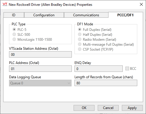
Configuration in the PCCC/DF1 tab is required to support the Data File addressing-compatible modes (PCCC over CIP, Legacy Serial/CSP Socket and Routed DH+).
PLC Type
Select the type of the target Allen-Bradley PLC. This may be one of:
- PLC-5
- SLC-500
- MicroLogix 1100-1500
VTScada Station Address (Octal)
Legacy Serial mode only. Specify the address (using the octal addressing format) of the VTScada system on the serial link.
PLC Address (Octal)
Legacy Serial and Routed DH+ modes only. This field should contain the octal address of the Allen-Bradley programmable logic controller.
DF1 Mode
Choose between the following data transmission modes in communications from the driver to the PLC.
- Full Duplex (Serial) is the same as the AB Driver's Serial 'Communication mode' and DF1 Mode of Full Duplex.
Full duplex mode refers to the transmission of data by both parties simultaneously. - Half Duplex (Serial) is the same as the AB Driver's Serial 'Communication mode' and DF1 Mode of Half Duplex.
Half duplex mode refers to the transmission of data in one direction at a time. If the driver and the PLC are communicating using the half duplex mode, either the driver or the PLC may transmit data at one time. The device not communicating must wait until the device that is transmitting data is finished before it can transmit its data. - Radio Modem (Serial) is the same as the AB Driver's Serial 'Communication mode' and DF1 Mode of Radio Modem.
Certain Allen Bradley PLCs use the Radio Modem Protocol (RMP) to optimize DF1 communication on radio modem links. The protocol is an enhancement of the Full Duplex Protocol and uses the same message format with all the ACK and NAK responses removed. - Multi-message Full Duplex (Serial) is the same as the AB Driver's Serial 'Communication mode' and the Multi-message mode checked.
If multiple Allen Bradley drivers are sharing the same port, then all drivers using the port must use the same configuration for this setting. Further, all of their "Communication Mode" and "DF1 Mode" settings must match as well. This option cannot be used if other types of drivers share the same port. - CSP Socket (TCP/IP) is the same as the AB Driver's TCP/IP Communication mode.
This is supported only by the PLC5 and SLC-500 PLCs, The MicroLogic TCP/IP uses the PCCC Mode of the Rockwell driver for its TCP/IP based communication.
BCC
Select whether the BCC error checking method will be used on communication messages. If not selected (the default) then CRC error checking is used on all communication messages.
The CRC acronym stands for Cyclic Redundancy Check, and the BCC acronym stands for Block Check Character. Both are techniques used to detect data transmission errors. In general, CRC is a better error checking method, as it is a 16-bit error check, whereas BCC is an 8-bit error check.
ENQ Delay
Specify the amount of time (in seconds or in fractions of a second) that this driver should wait before sending an ENQ when the DF1 mode is set to half duplex.
(Half duplex mode refers to the transmission of data in one direction at a time.)
Data Logging Queue
Use to select a queue (configured according to the PLC’s manual) from which the driver will be retrieving logged data.
Length of Records from Queue
Enter the length of the records in the queue selected in the Data Logging Queue drop list. This value is the length (in characters) of the records in the queue after they are converted into a string by the PLC for communication.
The valid range is from 1 to 80. The value must be calculated according to how the data logging queue was configured in the PLC itself:
- 11 characters for the date field,
- 9 characters for the time field,
- 12 characters for each long integer field
- 7 characters for each short integer field.
By default, the driver will assume a length of 80 chars (the maximum allowed by the PLC). While the default value will work, this may impose a penalty on the amount of communication between the driver and the PLC. Entering the exact length is therefore recommended.
Note: entering an incorrect value will most likely result in failure to read any records from a particular queue, therefore you should only change the default value if you know the exact value.
The following widgets are available to display information about your tags:
