
Counted towards your tag license limit.
This is a legacy tag type. You are advised to use the I/O and Calculations Tag instead.
Use this legacy type only if you are certain that it contains unique features that are absolutely necessary to your work.
Digital Control tags transmit digital data that is entered by the user or from another tag and write it to an I/O device.
A Digital Control tag might be used to turn a pump off or on, open a valve, or change the mode of a device from manual to auto.
Retained or Persisted values
Analog Control and Analog Output tags will both retain their last written value across application restarts. Use these tags when there is a need for a value to persist.
String I/O tags with output enabled, and with no driver ("No tag selected" rather than the default, "[*Driver] None found") will retain their last written value across application restarts.
The Digital Control and Digital Output tags do not have a similar feature, but an analog tag can be used in their place, writing a zero or a one. If the intent is to write a clear zero or one with an analog tag, both the scaled and unscaled range should be adjusted for a minimum value of zero and a maximum value of one, so that scaling does not adjust the values.
The ID tab of every tag includes the same common elements: Name, Area, Description, and Help ID.
Name:
Uniquely identifies each tag in the application. If the tag is a child of another, the parent names will be displayed in a separate area before the name field.
You may right-click on the tag's name to add or remove a conditional start expression.
Area
The area field is used to group similar tags together. By defining an area, you make it possible to:
- Filter for particular tag groups when searching in the tag browser.
- Link dial-out alarm rosters to Alarm tags having a particular area.
- Limit the number of tags loaded upon startup.
- Filter the alarm display to show only certain areas.
- Filter tag selection by area when building reports.
When working with Parent-Child tag structures, the area property of all child tags will automatically match the configured area of a parent. Naturally, you can change any tag's area as required. In the case of a child tag, the field background will turn yellow to indicate that you have applied an override. (Orange in the case of user-defined types. Refer to Configuration Field Colors).
To use the area field effectively, you might consider setting the same Area for each I/O driver and its related I/O tags to group all the tags representing the equipment processes installed at each I/O device. You might also consider naming the Area property for the physical location of the tag (i.e. a station or name of a landmark near the location of the I/O device). For serial port or Roster tags, you might configure the Area property according to the purpose of each tag, such as System or Communications.
You may define as many areas as you wish and you may leave the area blank for some tags (note that for Modem tags that are to be used with the Alarm Notification System, it is actually required that the area field be left blank).
To define a new area, type the name in the field. It will immediately be added. To use an existing area, use the drop-down list feature. Re-typing an existing area name is not recommended since a typo or misspelling will result in a second area being created.
There is no tool to remove an area name from VTScada since such a tool is unnecessary. An area definition will exist as long as any tag uses it and will stop existing when no tag uses it (following the next re-start).
Description
Tag names tend to be brief. The description field provides a way to give each tag a human-friendly note describing its purpose. While not mandatory, the description is highly recommended.
Tag descriptions are displayed in the tag browser, in the list of tags to be selected for a report and also on-screen when the operator holds the pointer over the tag’s widget. For installations that use the Alarm Notification System, the description will be spoken when identifying the tag that caused the alarm.
The description field will store up to 65,500 characters, but this will exceed the practical limits of what can be displayed on-screen.
This note is relevant only to those with a multilingual user interface:
When editing any textual parameter (description, area, engineering units...) always work in the phrase editor. Any changes made directly to the textual parameter will result in a new phrase being created rather than the existing phrase being changed.
In a unilingual application this makes no difference, but in a multilingual application it is regarded as poor practice.
Help Search Key
Used only by those who have created their own CHM-format context sensitive help files to accompany their application.
Digital Control properties I/O tab
The I/O Tab contains properties used to identify and establish a connection to the communication driver tag being used to exchange data with your physical I/O device (e.g. PLC or RTU), or to the Polling drive responsible for determining the order and rate at which data polls will occur.
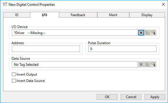
Digital Control - I/O Properties
I/O Device
Select the communication driver tag to which data will be written.
By default, the tag will look for a parent tag that is a device driver (..\*Driver). If none is found, the text "--Missing--" will be displayed. The tag button to the right of the field opens the tag browser, from which you can either select an existing communication driver tag or add a new one. The X button will clear the field. Right-clicking on a tag in the field will open a dialog with which you can add or remove a Parameter Expression or open a selected driver's properties dialog.
Address
Provide the address within the I/O device to which this tag is to write data. This value must match the configuration of your PLC or RTU hardware. Refer to the Addressing topic for your device driver for guidance.
For some drivers (SNMP and the OPC Classic Client) an address browser is provided to assist you.
Pulse Duration
If you are using a pulsed signal, enter the duration of the pulse here in seconds or decimal parts of a second.
If the value of Pulse Duration is 0 or blank (Invalid), then a constant value will be written to the I/O device.
A pulsed output is used to send a 1; seldom if ever, a zero. Use care with the configuration of the linked widget or multi-write tag.
Data Source
The value output by the control can be supplied by a data source. For a digital control, the values supplied by the data source should be limited to 1 or 0 (true or false).
Invert Output
Reverse the value of the output before writing.
Invert Data Source
Reverse the value coming from the data source before using.
Digital Control properties Feedback tab
The Feedback tab can be used to select an alarm, alarm priority, digital status, or Digital Control tag that will provide feedback when this tag's control action has successfully been completed.
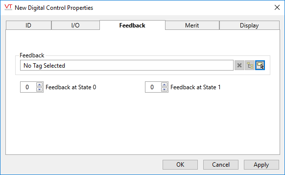
Digital Control - Feedback tab
Feedback
The Feedback field enables you to specify an existing alarm, alarm priority, digital status, or Digital Control tag whose value can be used to determine whether the control action for this tag was successful. When a value is output by this tag, the feedback tag reads its value from the I/O device at the same address, and compares this value with the expected value(s) configured in the Feedback At State 0 and Feedback At State 1 spin boxes (see following notes).
If the Pulse Duration property for this tag (as set on the I/O tab) is set to a valid value greater than 0 (i.e. a pulsed signal), then the Feedback At State 0 property is ignored, as the logic assumes that the control attempt is always to drive the value of the feedback tag to the Feedback At State 1 value.
The 0 state may be inverted to a 1 before writing to the I/O device if this tag's Invert Output property (I/O tab) is set to 1 (true).
Feedback At State 0
If the Pulse Duration property for this tag, as set on the I/O tab, is set to any of: 0 (the default), invalid, or blank (i.e. a non-pulsed signal) then...
The Feedback At State 0 spin box should be set to the value you expect for the selected Feedback tag when this tag has successfully gone to the 0 state. For example, if you've configured this tag to stop a motor by issuing a value of 0 to the I/O device, you would expect the feedback tag (e.g. a Digital Status tag) to read a 0 back from the I/O device, indicating that your output was received.
Feedback At State 1
If the Pulse Duration property for this tag, as set on the I/O tab, is set to any of: 0 (the default), invalid, or blank (i.e. a non-pulsed signal), then...
The Feedback At State 1 spin box can be used to set the value you expect for the feedback tag when this tag has successfully gone to the 1 state. For example, if you've configured this tag to stop a motor by issuing a value of 1 to the I/O device, you would expect that the feedback tag (e.g. a Digital Status tag) would read 1 back from the I/O device, indicating that the value was received.
This value can be used as the source for an Alarm tag with a time delay to alert the operator that the requested output change has not had the desired effect within a reasonable period of time.
Digital Control properties Merit tab
Privilege
Select a custom security privilege
Questionable Data
Use the Questionable Data parameter to flag this tag’s data in the event that you suspect the values it is reporting might not be accurate, or when this tag has initially been created and you wish to ensure that its data is marked for extra monitoring.
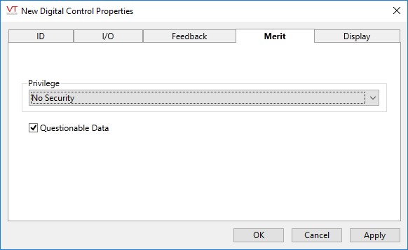
Digital Control - Merit tab
Digital Control properties Display tab
Style
When this tag is represented on screen by widgets that can use a Style Settings tag, you can save development time by choosing the Style Settings tag that holds the correct display configuration for this tag instance. (See: Style Settings Tags)
The default configuration will search for the first ancestor or then sibling tag of the Style Settings type. If there is none, it will use System Style, which is the default style tag that is automatically part of every new VTScada application.
Off Text
Optionally configure text that will be displayed in some of the tag's widgets when the value of this tag is 0 or false / off.
On Text
Optionally configure text that will be displayed in some of the tag's widgets when the value of the tag is 1 or true / on.
Display Order
Used to specify the placement of this tag when viewed in an associated station dialog. See Order tab for further details.
Digital Control tags enable users to write digital data to a PLC or RTU, which transmits the entered value to the equipment process associated with the tag. The widgets for Digital Control tags enable users to set values to be written to the equipment process associated with the tag, and display these set values.
The following widgets are available to Digital Control tags:
Equipment / Status Color Indicator
Legacy Set Value Button Widget
Legacy Set Value Hotbox Widget
Of the widgets displayed above, only the Momentary Button, Legacy Set Value Button, and Legacy Set Value Hotbox widgets allow users to actually output data to the equipment process associated with the tag being drawn. All other widgets simply display the current value of the tag, which will normally be zero while waiting to write.
Confirmation Prompts for Output Tags - Control options for confirmation prompt text.
