
This is a legacy tag type. You are advised to use the I/O and Calculations Tag instead.
Use this legacy type only if you are certain that it contains unique features that are absolutely necessary to your work.
Counted towards your tag license limit.
Digital inputs represent incoming digital data values from equipment, and provide widgets that change color, appearance, or text to impart the value of the digital input and associated equipment.
A Digital Input tag can be a single bit digital input or a double bit digital input. For single bit digital inputs, there are two possible states. For digital inputs that use two address bits, there are four possible states.
Digital inputs clamp raw data values to either zero or one on each input pin (yielding a result of 0, 1, 2, or 3 for pump status and Digital Status tags). Analog zero yields zero, while all other values yield 1. This is effective for analog values that have discrete states (e.g. line voltage can be read for on/off), but pure analog data (e.g. velocity) will only become false when the value drops below the sensitivity of the measuring device.
In most situations, use Digital Status Tags rather than Digital Input tags.
The ID tab of every tag includes the same common elements: Name, Area, Description, and Help ID.
Name:
Uniquely identifies each tag in the application. If the tag is a child of another, the parent names will be displayed in a separate area before the name field.
You may right-click on the tag's name to add or remove a conditional start expression.
Area
The area field is used to group similar tags together. By defining an area, you make it possible to:
- Filter for particular tag groups when searching in the tag browser.
- Link dial-out alarm rosters to Alarm tags having a particular area.
- Limit the number of tags loaded upon startup.
- Filter the alarm display to show only certain areas.
- Filter tag selection by area when building reports.
When working with Parent-Child tag structures, the area property of all child tags will automatically match the configured area of a parent. Naturally, you can change any tag's area as required. In the case of a child tag, the field background will turn yellow to indicate that you have applied an override. (Orange in the case of user-defined types. Refer to Configuration Field Colors).
To use the area field effectively, you might consider setting the same Area for each I/O driver and its related I/O tags to group all the tags representing the equipment processes installed at each I/O device. You might also consider naming the Area property for the physical location of the tag (i.e. a station or name of a landmark near the location of the I/O device). For serial port or Roster tags, you might configure the Area property according to the purpose of each tag, such as System or Communications.
You may define as many areas as you wish and you may leave the area blank for some tags (note that for Modem tags that are to be used with the Alarm Notification System, it is actually required that the area field be left blank).
To define a new area, type the name in the field. It will immediately be added. To use an existing area, use the drop-down list feature. Re-typing an existing area name is not recommended since a typo or misspelling will result in a second area being created.
There is no tool to remove an area name from VTScada since such a tool is unnecessary. An area definition will exist as long as any tag uses it and will stop existing when no tag uses it (following the next re-start).
Description
Tag names tend to be brief. The description field provides a way to give each tag a human-friendly note describing its purpose. While not mandatory, the description is highly recommended.
Tag descriptions are displayed in the tag browser, in the list of tags to be selected for a report and also on-screen when the operator holds the pointer over the tag’s widget. For installations that use the Alarm Notification System, the description will be spoken when identifying the tag that caused the alarm.
The description field will store up to 65,500 characters, but this will exceed the practical limits of what can be displayed on-screen.
This note is relevant only to those with a multilingual user interface:
When editing any textual parameter (description, area, engineering units...) always work in the phrase editor. Any changes made directly to the textual parameter will result in a new phrase being created rather than the existing phrase being changed.
In a unilingual application this makes no difference, but in a multilingual application it is regarded as poor practice.
Help Search Key
Used only by those who have created their own CHM-format context sensitive help files to accompany their application.
Digital Input properties I/O tab
The I/O tab holds the properties used to identify and establish a connection to the communication driver tag being used to exchange data with your physical I/O device (e.g. PLC or RTU). This is done by identifying the communication driver tag that communicates with the physical I/O device, the address at the physical I/O device from which this tag is to read its data, and the rate at which the I/O device should be scanned for data.
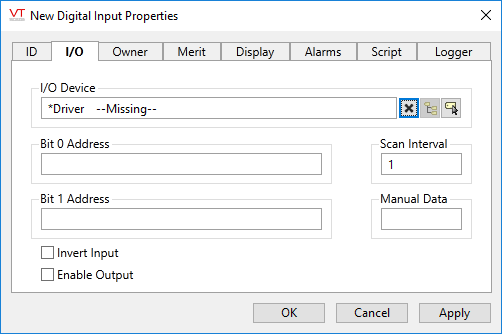
I/O Device
Select the communication driver tag from which data will be read.
By default, the tag will look for an ancestor or sibling tag that is a device driver (*Driver). If none is found, the text "--Missing--" will be displayed. If more than one equally qualified tags are found, "--Error: Multiple Drivers--" will be displayed. The tag button to the right of the field opens the tag browser, from which you can either select an existing communication driver tag or add a new one. The X button will clear the field. Right-clicking on a tag in the field will open a dialog with which you can add or remove a Snapshot Expression or open a selected driver's properties dialog.
Bit 0 Address
The Bit 0 Address property is the address of the low order bit for this tag in the I/O device. If this is a single bit digital tag, this is the field that specifies the address of that bit.
Address Assist:
Several drivers including SNMP, OPC Classic Client, Fisher ROC and others, provide an Address Assist button to help you. The content of the dialog will vary according to the driver. Within this guide, refer to the Driver Addressing topic for your driver for more information.
Bit 1 Address
The Bit 1 Address property is the address of the high order bit for the digital input in the I/O device. If this is a single bit digital input, this field should be left blank. See following notes on single bit and double bit inputs.
Scan Interval
Provide the frequency, measured in seconds, at which the I/O device should be scanned for new data. Reduce system load by setting this as high as possible, as appropriate for the equipment being monitored. If the I/O Device is a Polling driver, which provides its own scan interval, then this field will not accept data. Otherwise, try to keep scan intervals the same, so far as is reasonable, so that drivers can group (coalesce) reads from equipment where you have sequential addresses.
Manual Data
Sets a constant value that will be used instead of live data. Use when testing a new tag if you need to check behavior when a value is outside the normal operating range. Tags that have manual data are marked by a flashing exclamation mark within any linked widgets. Logged values are marked with an exclamation. Always reset this to blank after testing.
Invert Input
The Invert Input check box enables you to specify whether the value of this tag should be reversed. If selected, the value for this tag will be inverted (i.e. 0 and 1 are swapped).
The typical use for input inversion is in projects where 1 indicates false or off, and 0 indicates true or on. By default, the Invert Input check box is not selected.
Enable Output
If selected, this input tag may also be used to write data to the specified Bit 0 address of the communication driver. Pulsed writes are not available. A Security Privilege may be set in the Merit tab to restrict access to this feature.
Publisher
Select a Publisher tag if one is required for your configuration. Defaults to [*Publisher]. Eligible tags (Publisher tags that are a direct ancestor, uncle or sibling) will automatically link or you can select a tag manually. VTScada publishing configurations may include:
- An OPC client when your application has a properly-configured OPC Classic Server Setup tag.
- A Sparkplug B Edge Node or a Sparkplug B Edge Device.
- A MultiSpeak interface if properly configure. See: MultiSpeak Support.
- A Data Diode publisher or client tag.
Publish
This tag will publish data if a publisher is configured and this setting is enabled. If this setting is disabled, the tag will stop publishing data.
Single Bit and Double Bit Digital Inputs
A single bit digital status reads a value of 0 or a 1 from one address on an I/O device. An example of a single bit digital status would be a pump's status, where the pump is either off (0), or on (1).
A double bit digital status reads a value of 0 or 1 from two addresses on an I/O device. An example of an equipment process requiring a double bit digital status might be a valve with 4 states: open, closed, open or close action in progress, or error. The following table shows the possible values for a double bit digital status according to the values at each bit.
| State | Bit 1 | Bit 0 | Description | Tag Value |
|---|---|---|---|---|
| State 0 | 0 | 0 | A process is in action (either the valve is opening, or is closing) | 0 |
| State 1 | 0 | 1 | The valve is closed. | 1 |
| State 2 | 1 | 0 | The valve is open. | 2 |
| State 3 | 1 | 1 | There is an error. | 3 |
| Invalid | Invalid | Invalid | No data. | Invalid |
Digital Input properties Owner tab
This tag can be used in an owner/contributor structure where multiple contributor tags can supply their values to an owner tag.
There is no specific "owner" tag type, rather an owner tag is typically a custom-designed tag that is created using VTScada scripting code.
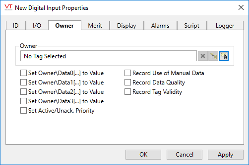
Owner
Specify a tag to which this contributor should supply its data. An owner tag is one which you must design and then create, using the VTScada scripting language.
The owner tag may keep track of different aspects of each contributor's data, from the presence of a user-defined manual data value, to questionable data, according to the configuration of the check boxes appearing beneath the Owner field. These check boxes also determine the way that this contributor tag's value should be used in the owner tag's calculations.
Set Owner\DataX(…) to Value
When selected, the Set Owner\DataX[…] To Value check box is used to set the value of this contributor tag as the nth element in the owner tag's array. You may choose to set this contributor tag's value in more than one of the owner tag's array elements if required.
Set Active/Unack. Priority
An owner tag may keep track of the alarm priority and status of its contributors. When selected, the Set Active/Unack. Priority check box causes the owner tag to keep track of the priority of the contributor's active alarm (or records an Invalid if the contributor is not in an alarm state). Selecting the Set Active/Unack. Priority check box also causes the owner tag to record whether the alarm has been acknowledged.
Record Use of Manual Data
An owner tag may keep track of the number of contributor tags that are providing manual data (user-defined values), rather than reading data from their I/O device. When selected, the Record Use of Manual Data check box is used to increment the owner's count of the number of tags that are contributing manual data by 1 when manual data has been provided for this contributor, and decrement this count by 1 when no manual data value has been specified.
Record Data Quality (Analog and Digital Input only)
An owner tag may keep track of the quality of the data for each of its contributors. When selected, the Record Tag Quality check box is used to increment the owner tag's count of the number of tags that are contributing quality data by 1, and decrement this count by 1 when this contributor is not supplying quality data.
Record Tag Validity
An owner tag may keep track of the questionable status of the data for each of its contributors. When selected, the Record Tag Validity check box is used to increment the owner tag's count of the number of tags that are contributing questionable data by 1, and decrement this count by 1 when this contributor is not supplying questionable data.
Digital Input properties Merit tab
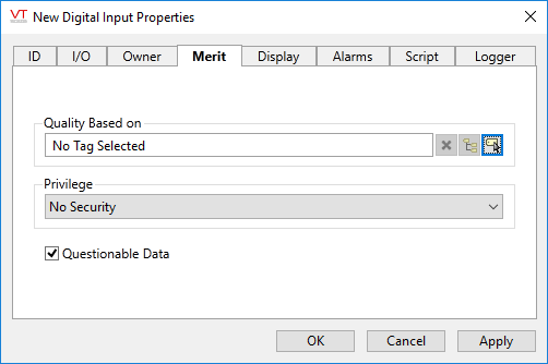
Quality Based on
The Quality Based On field is for use when this tag is to be a contributor to a custom-built container tag. Please see the topic Merit tab and Quality tab, for details.
Privilege
Select a custom security privilege
Questionable Data
Use the Questionable Data parameter to flag this tag’s data in the event that you suspect the values it is reporting might not be accurate, or when this tag has initially been created and you wish to ensure that its data is marked for extra monitoring.
Digital Input properties Display tab
When this tag is represented on screen by widgets that can use a Style Settings tag, you can save development time by choosing the Style Settings tag that holds the correct display configuration for this tag instance.
The default configuration will use System Style, the default style tag that is automatically part of every new VTScada application. If a Style Settings tag is an ancestor or else a sibling, it will become the new automatic default.

Digital Input properties Alarm tab
If you want this tag to trigger an alarm, use the Add button to open a configuration panel for a new Alarm tag. The triggered-by field for the new alarm will automatically be linked to this tag’s value. The new alarm tags will be created as children of the current tag.Digital Input properties Script tab
Optionally, link one or more Script tags to this tag. A Script tag provides a means of creating a procedure, using VTScada’s programming language, that will run whenever this tag’s value changes.
Digital Input properties Logger tab
The logger tab enables you to associate a single Logger tag with this tag. The Logger tag and the attached Historian will record this tag’s data to disk so that it can be plotted on the Historical Data Viewer page. The new logger tag will be created as a child of the current tag.
Only one Logger tag can be directly associated with a single input or output tag. If you need to have multiple loggers with different logging rates, please refer to Using Function Tags to Create Multiple Data Logs of an I/O Tag
The following widgets are available to display information about your application’s Digital Input tags:
Equipment / Status Color Indicator
Legacy Set Value Button Widget
