
This is a legacy tag type. You are advised to use the I/O and Calculations Tag instead.
Use this legacy type only if you are certain that it contains unique features that are absolutely necessary to your work.
An I/O tag with a data type of Digital and an equipment type set to Pump will serve the same purpose as the legacy Pump Status tag.
Counted towards your tag license limit.
Pump status tags accept incoming digital data from pumps. These are similar to Digital Status tags, but are designed specifically for use with pumps. predefined reports, including Pump Activity and Pump Discrepancy are designed to work with data from Pump Status tags.
Digital inputs, including Pump Status tags, clamp raw data values to either zero or one on each input pin (yielding a result of 0, 1, 2, or 3 for Pump Status and Digital Status tags). Analog zero yields zero, while all other values yield 1. This is effective for analog values that have discrete states (e.g. line voltage can be read for on/off), but pure analog data (e.g. velocity) will only become false when the value drops below the sensitivity of the measuring device.
The ID tab of every tag includes the same common elements: Name, Area, Description, and Help ID.
Name:
Uniquely identifies each tag in the application. If the tag is a child of another, the parent names will be displayed in a separate area before the name field.
You may right-click on the tag's name to add or remove a conditional start expression.
Area
The area field is used to group similar tags together. By defining an area, you make it possible to:
- Filter for particular tag groups when searching in the tag browser.
- Link dial-out alarm rosters to Alarm tags having a particular area.
- Limit the number of tags loaded upon startup.
- Filter the alarm display to show only certain areas.
- Filter tag selection by area when building reports.
When working with Parent-Child tag structures, the area property of all child tags will automatically match the configured area of a parent. Naturally, you can change any tag's area as required. In the case of a child tag, the field background will turn yellow to indicate that you have applied an override. (Orange in the case of user-defined types. Refer to Configuration Field Colors).
To use the area field effectively, you might consider setting the same Area for each I/O driver and its related I/O tags to group all the tags representing the equipment processes installed at each I/O device. You might also consider naming the Area property for the physical location of the tag (i.e. a station or name of a landmark near the location of the I/O device). For serial port or Roster tags, you might configure the Area property according to the purpose of each tag, such as System or Communications.
You may define as many areas as you wish and you may leave the area blank for some tags (note that for Modem tags that are to be used with the Alarm Notification System, it is actually required that the area field be left blank).
To define a new area, type the name in the field. It will immediately be added. To use an existing area, use the drop-down list feature. Re-typing an existing area name is not recommended since a typo or misspelling will result in a second area being created.
There is no tool to remove an area name from VTScada since such a tool is unnecessary. An area definition will exist as long as any tag uses it and will stop existing when no tag uses it (following the next re-start).
Description
Tag names tend to be brief. The description field provides a way to give each tag a human-friendly note describing its purpose. While not mandatory, the description is highly recommended.
Tag descriptions are displayed in the tag browser, in the list of tags to be selected for a report and also on-screen when the operator holds the pointer over the tag’s widget. For installations that use the Alarm Notification System, the description will be spoken when identifying the tag that caused the alarm.
The description field will store up to 65,500 characters, but this will exceed the practical limits of what can be displayed on-screen.
This note is relevant only to those with a multilingual user interface:
When editing any textual parameter (description, area, engineering units...) always work in the phrase editor. Any changes made directly to the textual parameter will result in a new phrase being created rather than the existing phrase being changed.
In a unilingual application this makes no difference, but in a multilingual application it is regarded as poor practice.
Help Search Key
Used only by those who have created their own CHM-format context sensitive help files to accompany their application.
Pump Status properties I/O tab
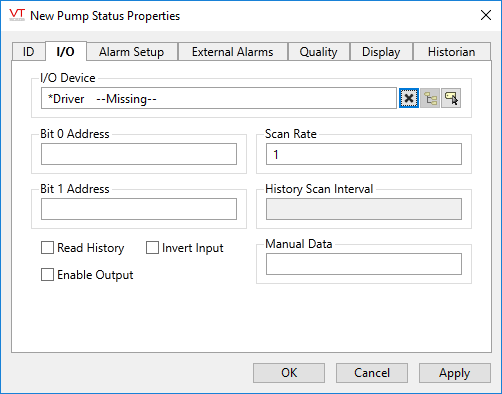
The I/O tab holds the properties used to identify and establish a connection to the communication driver tag being used to exchange data with your physical I/O device (e.g. PLC or RTU), or to the polling driver responsible for determining the order and rate at which data polls will occur.
Pump status tags can have single or double bit addresses.
I/O Device
Select the communication driver tag from which data will be read.
By default, the tag will look for an ancestor or sibling tag that is a device driver (*Driver). If none is found, the text "--Missing--" will be displayed. If more than one equally qualified tags are found, "--Error: Multiple Drivers--" will be displayed. The tag button to the right of the field opens the tag browser, from which you can either select an existing communication driver tag or add a new one. The X button will clear the field. Right-clicking on a tag in the field will open a dialog with which you can add or remove a Snapshot Expression or open a selected driver's properties dialog.
Bit 0 Address
The Bit 0 Address property is the address of the low order bit for this tag in the I/O device. If this is a single bit digital tag, this is the field that specifies the address of that bit. The reported value of this digital tag is the data at this address plus two times the data at the Bit 1.
Note: If a data logger is being used on a tag, it can only be for a single bit address.
Bit 1 Address
The Bit 1 Address property is the address of the high order bit for the digital input in the I/O device. If this is a single bit digital input, this field should be left blank.
Scan Rate
Provide the frequency, measured in seconds, at which the I/O device should be scanned for new data. Reduce system load by setting this as high as possible, as appropriate for the equipment being monitored. If the I/O Device is a Polling driver, which provides its own scan interval, then this field will not accept data. Otherwise, try to keep scan intervals the same, so far as is reasonable, so that drivers can group (coalesce) reads from equipment where you have sequential addresses.
Read History
If selected, the field Bit 0 Address becomes History Address and the field History Scan Interval is enabled.
History Address
If set, then the Bit 0 address becomes optional. This field provides a means of reading values as recorded by a data logger.
If both the Bit 0 address and the history address are provided, then the Bit 0 address will be polled for data at the interval set by the Scan Rate, but the values read from the data logger will overwrite the values logged by this tag when it is updated.
The form for the history address will depend on the RTU. Please refer to the addressing reference chapter for your driver.
History Scan Interval
Sets the time between polls of the history data logger. If a History address has been set, but this field is left blank, then it will default to the value set in the Scan Rate field. The recommended value for this field is 60 seconds. Lesser values may cause communications to slow down.
Manual Data
Sets a constant value that will be used instead of live data. Use when testing a new tag if you need to check behavior when a value is outside the normal operating range. Tags that have manual data are marked by a flashing exclamation mark within any linked widgets. Logged values are marked with an exclamation. Always reset this to blank after testing.
Invert Input
If the Invert Input check box is selected, the value of the tag being used as the data source is reversed (i.e. a 1 becomes a 0 or a 0 becomes a 1) before it is written to the I/O device.
Enable Output
If selected, this input tag may also be used to write data to the specified Bit 0 address of the communication driver. A Security Privilege may be set in the Quality tab to restrict access to this feature.
Publisher
Select a Publisher tag if one is required for your configuration. Defaults to [*Publisher]. Eligible tags (Publisher tags that are a direct ancestor, uncle or sibling) will automatically link or you can select a tag manually. VTScada publishing configurations may include:
- An OPC client when your application has a properly-configured OPC Classic Server Setup tag.
- A Sparkplug B Edge Node or a Sparkplug B Edge Device.
- A MultiSpeak interface if properly configure. See: MultiSpeak Support.
- A Data Diode publisher or client tag.
Publish
This tag will publish data if a publisher is configured and this setting is enabled. If this setting is disabled, the tag will stop publishing data.
Pump Status properties Alarm Setup tab
Optionally configure one alarm based on the status of this tag. Note that, while the priority is set to "None" all other controls are disabled.
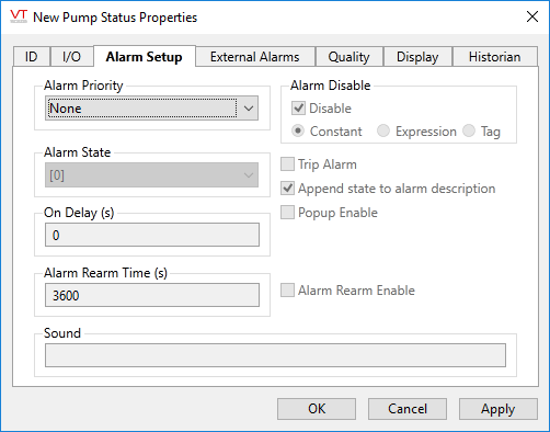
Alarm Priority
The Alarm Priority drop-down list enables you to select the priority of the alarm that will be triggered for this tag. The available priorities are:
- None
- 0 - Event
- 1 - Critical Alarm
- 2 - High Alarm
- 3 - Warning Alarm
- 4 - Notice Alarm
If you have defined your own Alarm Priority tags, those will also be available for selection.
Alarm State
The Alarm State spin box enables you to select the trigger for the alarm. The alarm will be triggered when the tag's state becomes one of the following:
0 The alarm is triggered when Bit 0 goes low. The Bit 1 address either has not been provided or is low.
1 The alarm is triggered when Bit 0 goes high. The Bit 1 address either has not been provided or is low.
2 Two addresses provided. Bit 0 goes low and Bit 1 goes high.
3 Two addresses provided. Both Bit 0 and Bit 1 go high.
Upon Change - any change of state triggers an alarm. Note that when the Upon Change option is selected, the trip alarm option will be set and cannot be deselected by the developer.
On Delay
Transient changes in state can result in multiple alarms being triggered. By setting an alarm delay, you can specify that if the tag’s state changes back one which does not constitute an alarm situation, it must remain in that state for a given length of time before the alarm is deemed to be inactive.
Alarm Rearm Time
Applies only if Alarm Rearm Enable is selected for this alarm. If the alarm has been acknowledged, but remains active for the time shown in this field, the alarm will return to the unacknowledged state. Audible and visible warnings configured for this alarm’s priority level, will again be displayed. The Alarm Rearm Time is measured in seconds, and defaults to 3600 (1 hour). The value in this field must be greater than 0.
Alarm Rearm Enable
Controls whether this alarm will revert back to an unacknowledged state if it remains active for the length of time set in Alarm Rearm Time, after having been acknowledged by the operator.
Alarm Disable
Specify whether the low alarm for this tag is disabled or enabled. Disabling of alarms is typically used in situations where you wish to avoid false alarms. For example, in the event that routine maintenance is being performed on the equipment represented by this tag, or when you are aware that another interruption in communications will occur for a period of time. In such situations, the alarm can be disabled until the maintenance is complete and communications are reestablished.
May be linked to a tag or expression for suppression by design.
The following is an advanced configuration technique. If you do not need to toggle alarm disabling on hundreds of alarms on a frequent basis, this technique is not appropriate for your application.
Each time you toggle an alarm between enabled and disabled, an event is recorded. If you must repeat this operation frequently for hundreds of tags, a large number of events can be recorded.
As an alternative, you could create a non-optimized expression for the alarm setpoint that toggles between the real setpoint and one that is either so high or so low that it can never cause the alarm to trigger. Changes made to the setpoint this way do not result in events being recorded.
Trip Alarm
Select if this alarm is to be a trip alarm.
Trip alarms differ from level alarms in that they are not active or inactive based on the value of the Trigger tag. After alarms are triggered, they must be acknowledged, but there is no requirement that the cause of the alarm condition be cleared.
Append State to Alarm Description
When selected, VTScada will append the text used for the state of the tag, as taken from the Off Text and On Text fields in the tag’s I/O tab, to the alarm message.
Pop-up Enable
If the configuration variable AlarmPopupsEnable is set to 1, then setting either the Low Alarm Pop-up Enable or the High Alarm Pop-up Enable, will result in a pop-up dialog being displayed whenever the respective alarm is triggered. It is strongly suggested that this feature be used sparingly.
Sound
The Sound field can be set to blank, 0, 1, or to the name of a .WAV sound file to be played.
If 0, no sound will be played when this alarm is triggered.
If blank or 1, an alarm sound whose properties are configured on the associated Alarm Priority tag will be played.
If the name of a .WAV sound file, it will override any alarm sound configured for the associated Alarm Priority tag. If the specified sound file is not found, the alarm will revert to using tones as specified in the associated Alarm Priority tag.
Pump Status properties External Alarms tab
The External Alarms tab is used to display, add or remove separate Alarm tags that are triggered by this Pump Status tag. Use the Add button to create new external Alarm tags and the Delete button to remove them. The new alarm tags will be created as children of the current tag.
Pump Status properties Quality tab
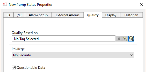
Quality Based On
The Quality Based On field can be tied to a driver tag, a tag that monitors driver communication errors, a register in the PLC or RTU, or any other indication of system health. The tag you are configuring will use that value to set an internal variable named QualityIssue. You may test this value in an expression: [TagName]\QualityIssue.
QualityIssue will be a 0 or 1. "Good Quality" is defined as a value of "0 or Invalid" and "Bad Quality" is defined as any valid, non-zero value. This is consistent with driver communication error values.
Widgets that use the System Style tag will display bad quality using the color set on the Exceptions tab.
Privilege
Select a custom security privilege
Questionable data
Use the Questionable Data parameter to flag this tag’s data in the event that you suspect the values it is reporting might not be accurate, or when this tag has initially been created and you wish to ensure that its data is marked for extra monitoring.
Pump Status properties Display tab
Style
When this tag is represented on screen by widgets that can use a Style Settings tag, you can save development time by choosing the Style Settings tag that holds the correct display configuration for this tag instance. (See: Style Settings Tags)
The default configuration will search for the first ancestor or then sibling tag of the Style Settings type. If there is none, it will use System Style, which is the default style tag that is automatically part of every new VTScada application.
Off Text and On Text
Certain widgets will display the text you configure here. This text will also be used in confirmation boxes for the control action (if configured).
Display Order
Used to specify the placement of this tag when viewed in an associated station dialog. See Order tab for further details.
Pump Status properties Historian tab
Historian
If an Historian tag is selected, this tag's run-time values will be saved for use in reports and the Historical Data Viewer. Historian configuration and advanced logging options are described in the discussion of the Historian Tags.
If your goal is to disable logging, set the Enable parameter (below) to 0 rather than deleting the Historian parameter.
There are consequences if you change the selected Historian tag after you have begun collecting data. If you switch to a new Historian (perhaps for organizational or load sharing purposes), the data collected for this tag by the previous Historian will become inaccessible. Historian selection and configuration should be done during the project design stage.
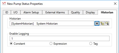
Enable Logging
If values should be logged only while certain conditions are true, you can tie the Enable Logging option to any tag or expression that will change from zero (logging disabled) to non-zero (usually 1; logging enabled).
The following widgets are available to display information about your application’s Pump Status tags:
