
Counted towards your tag license limit.
Selector Switch tags provide the means to create multi-position switches that can be used to create on-off toggles, mode selectors, or Hand-Off-Auto (H-O-A) switches.
Reference Notes:
For each switch position, a predefined value will be written to a specific address. Each position can write to the same address, or each could write to a unique address. Using the same address is typical for toggle switches. Using unique addresses is typical for Hand-Off-Auto (HOA) switches. If a unique address is used for each switch position, it is customary to configure the switch to write a zero to the address for each position not currently selected.
Selector Switches can be used as digital controls, but they differ in structure from I/O tags that do digital control. Use care when choosing which type to use for any situation.
Feedback
A Selector Switch can accept two types of feedback:
- Equipment feedback indicates the current status or state of the equipment. When configuring the Selector, you can specify what the expected value will be for each switch position.
- Switch Position feedback updates the selected position of the Selector Switch. This value must match the numeric switch position (0, 1, or 2). A new value arriving via the position feedback does not cause the Selector Switch tag to do a fresh write.
In both cases, feedback must be provided by a tag or an expression.
The two types of feedback do two different things and either (or both) should be used as needed. Switch position feedback must be used if something other than VTScada can change the position or mode of that item.
Mismatch Conditions
The selector switch is designed to alert the operator to a mismatch condition by providing visual feedback through its native widgets.
There are two possible causes for a mismatch condition:
- Position mismatch The switch position as requested by the operator does not match the actual position as reported by the switch position feedback value. This can occur when there is a lag in response time from the equipment.
- Value mismatch The equipment feedback does not match the expected value for the requested or current position. This type of mismatch can also be used to trigger an alarm. The alarm must be enabled and the mismatch must exist for a set length of time before an alarm will become active.
The native widgets for the selector switch will use the following conventions to notify the operator of a mismatch or an alarm condition:
- Alarm indicators take precedence. While an alarm indicator is active, no other mismatch indicator will be displayed.
- Alarms are normally indicated with red, and (if possible) will be shown on the requested or current position of the switch.
- Alarm indicators are displayed until the alarm condition is cleared, regardless of whether the alarm has been acknowledged.
- When a position mismatch occurs and no alarm state is active, then (if possible) the requested position will be indicated by the widget - often by blinking.
- When a value mismatch occurs and the alarm is either disabled or has not yet triggered, an indication like a position mismatch will be displayed, if possible.
The ID tab of every tag includes the same common elements: Name, Area, Description, and Help ID.
Name:
Uniquely identifies each tag in the application. If the tag is a child of another, the parent names will be displayed in a separate area before the name field.
You may right-click on the tag's name to add or remove a conditional start expression.
Area
The area field is used to group similar tags together. By defining an area, you make it possible to:
- Filter for particular tag groups when searching in the tag browser.
- Link dial-out alarm rosters to Alarm tags having a particular area.
- Limit the number of tags loaded upon startup.
- Filter the alarm display to show only certain areas.
- Filter tag selection by area when building reports.
When working with Parent-Child tag structures, the area property of all child tags will automatically match the configured area of a parent. Naturally, you can change any tag's area as required. In the case of a child tag, the field background will turn yellow to indicate that you have applied an override. (Orange in the case of user-defined types. Refer to Configuration Field Colors).
To use the area field effectively, you might consider setting the same Area for each I/O driver and its related I/O tags to group all the tags representing the equipment processes installed at each I/O device. You might also consider naming the Area property for the physical location of the tag (i.e. a station or name of a landmark near the location of the I/O device). For serial port or Roster tags, you might configure the Area property according to the purpose of each tag, such as System or Communications.
You may define as many areas as you wish and you may leave the area blank for some tags (note that for Modem tags that are to be used with the Alarm Notification System, it is actually required that the area field be left blank).
To define a new area, type the name in the field. It will immediately be added. To use an existing area, use the drop-down list feature. Re-typing an existing area name is not recommended since a typo or misspelling will result in a second area being created.
There is no tool to remove an area name from VTScada since such a tool is unnecessary. An area definition will exist as long as any tag uses it and will stop existing when no tag uses it (following the next re-start).
Description
Tag names tend to be brief. The description field provides a way to give each tag a human-friendly note describing its purpose. While not mandatory, the description is highly recommended.
Tag descriptions are displayed in the tag browser, in the list of tags to be selected for a report and also on-screen when the operator holds the pointer over the tag’s widget. For installations that use the Alarm Notification System, the description will be spoken when identifying the tag that caused the alarm.
The description field will store up to 65,500 characters, but this will exceed the practical limits of what can be displayed on-screen.
This note is relevant only to those with a multilingual user interface:
When editing any textual parameter (description, area, engineering units...) always work in the phrase editor. Any changes made directly to the textual parameter will result in a new phrase being created rather than the existing phrase being changed.
In a unilingual application this makes no difference, but in a multilingual application it is regarded as poor practice.
Help Search Key
Used only by those who have created their own CHM-format context sensitive help files to accompany their application.
Selector Switch properties I/O tab
The I/O Tab includes properties used to identify and establish a connection to the communication driver tags being used to exchange data with your physical I/O device (e.g. PLC or RTU). This is done by identifying the communication driver tag that is linked with the physical I/O device.
In addition, the I/O tab also provides a means of selecting tags or expressions that are to provide feedback for the state of the equipment or external control over the switch position.
Feedback versus Switch Position Feedback
Feedback is a value that you read from the controller by configuring a tag to monitor an address on the controller. By monitoring a feedback value, you can ensure that the correct value was written after changing the switch position, and that the controller and the SCADA system agree on the current switch position.
Referring to the labels from the configuration panel (see following image):
Feedback
The Feedback field is used to ensure that the correct value was written to the remote device. This is similar to the feedback field of a Digital Control tag. When configuring the switch positions and the value to write for each position, you will also configure the value that will be expected via the feedback for each position of the switch.
If the value of the selected feedback tag or expression does not match the expected value for the current position, then this will trigger an alarm, assuming that the alarm option of the selector has been enabled.
Switch Position Feedback
Switch Position Feedback is used to ensure that the selector in the SCADA system remains synchronized with the controller. The tag or expression used for this field must be able to have values matching the possible positions of the selector. (0 and 1 for a two-position selector, 0, 1 and 2 for a three-position selector).
If the tag or expression providing position feedback changes to a new value, this Selector Switch will update to match. Note that this does not cause the tag to do a fresh write to the equipment.
If an operator changes the position of this Selector Switch within the application, but the switch position feedback indicates that the physical position has not changed, the widget will blink to show a mismatch.
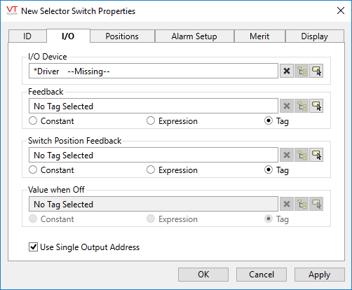
I/O configuration for a Selector Switch
I/O Device
Select the communication driver tag to which data will be written.
By default, the tag will look for a parent tag that is a device driver (..\*Driver). If none is found, the text "--Missing--" will be displayed. The tag button to the right of the field opens the tag browser, from which you can either select an existing communication driver tag or add a new one. The X button will clear the field. Right-clicking on a tag in the field will open a dialog with which you can add or remove a Snapshot Expression, or open a selected driver's properties dialog.
Feedback (equipment feedback)
[Optional] Select the tag or expression that has been configured to provide feedback indicating whether the control action of this switch has been successful. "Success" means that the state of the equipment matches what is expected (as configured on the Positions tab) for each possible switch position. A mismatch in values here will trigger an alarm, if one is configured on the Alarm Setup tab.
Switch Position Feedback
[Optional] Select the tag or expression that has been configured to provide an indication of the current position of the equipment. (0, 1 or 2 according to switch positions) The selector switch will change positions to follow this feedback value. If the selector switch is changed, but the feedback value does not follow, the widget will blink, but this will not by itself cause an alarm. See Feedback (equipment feedback).
Value When Off
Available only when the Use Single Output Address option has been deselected. The value provided here will be written to the addresses of the unselected switch positions after the current position's value has been written.
Use Single Output Address
This check box provides an option to use a single output address for all switch positions, or to allow a separate address for each position.
In the case where each position of the switch writes to a different output address, you can deselect the "Use Single Output Address" box and provide a value that will be written to each address not matching the current switch position. Note: Addresses are specified on the next tab, Positions.
Values will be written in a "make before break" order. In other words, the value for a new switch position will always be written before the value-when-off is written to the addresses matching the unselected switch positions
Publisher
Select a Publisher tag if one is required for your configuration. Defaults to [*Publisher]. Eligible tags (Publisher tags that are a direct ancestor, uncle or sibling) will automatically link or you can select a tag manually. VTScada publishing configurations may include:
- An OPC client when your application has a properly-configured OPC Classic Server Setup tag.
- A Sparkplug B Edge Node or a Sparkplug B Edge Device.
- A MultiSpeak interface if properly configure. See: MultiSpeak Support.
- A Data Diode publisher or client tag.
Publish
This tag will publish data if a publisher is configured and this setting is enabled. If this setting is disabled, the tag will stop publishing data.
Selector Switch properties Positions tab
In the Positions tab you can configure the expected feedback values, the values to write and the address(es) corresponding to each of the possible switch positions. (Whether a single or multiple output addresses are used, depends on the check box in the I/O panel.)
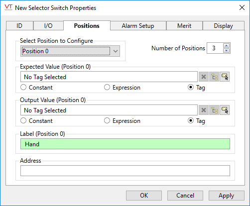
Select Position to Configure
Select each of the available switch positions to configure the output and expected values for that position. The label over each parameter will change to show which position is being configured. The list is controlled by the parameter, Number of Positions.
Number of Positions
May be either "2" or "3". Limits the number of configurable positions in the switch. Always select "2" for a toggle switch. (This differs from earlier versions where it was common practice to create toggle switches by configuring positions "0" and "2," leaving position "1" blank.)
Expected Value (Position x)
Specify the value that is expected to be returned in the feedback field of the I/O panel, to indicate that the tag's switching operation caused a successful change in the system. This value can be a constant, an expression, or it may come from a tag.
Output Value (Position x)
This field is where you to specify the constant, expression or tag value that will be written to the output address when the corresponding position is selected. If a tag or expression is used here, then changing output values will trigger a write to the device as long as the position has not changed.
Label (Position x)
If the switch requires operator confirmation (configured when drawing the switch as a toggle) then this label will appear as part of the confirmation prompt for the matching switch position.
Address
The I/O address to write the output value to when position x is selected.
If the Use Single Address option was checked in the I/O panel, then this field will be labeled simply "Address" since the same address is used for all positions. Otherwise, the label will be "Address (Position x)" to indicate which switch position you are providing the address for.
Selector Switch properties Alarm Setup tab
Specify the parameters of the alarm that will be triggered when the equipment feedback for the tag does not match expected value.
Because physical equipment can sometimes take a few moments to respond, a delay can be specified to prevent the alarm from being triggered while waiting for the expected feedback value.
By design, this alarm cannot be configured as a trip alarm.
Invalid data, whether on the I/O Device or a feedback tag, will neither cause nor clear an alarm condition.
Tag parameter expressions have "Optimize to only evaluate at tag initialization" selected by default.
Do not deselect this option for alarm parameter expressions. Do not use non-optimized expressions for alarm parameters.
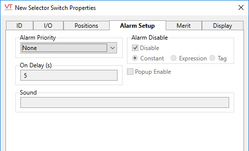
Alarm Priority
Select the priority level of this alarm. All other controls are disabled while the priority level is set to "None".
On Delay
Specify a delay in seconds to wait when the feedback value from the PLC does not match the expected value for the requested switch position before triggering an alarm.
Sound
[optional] Enter the name of a .wav file in your application directory to use that as the alarm sound.
Alarm Disable
Deselect to enable alarms on this switch. May be linked to a tag or expression for suppression by design.
Pop-up Enable
Available only when alarm pop-ups are enabled in the application properties (see: AlarmPopupsEnable)
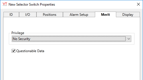
Selector Switch properties Merit tab
Use the Questionable Data parameter to flag this tag’s data in the event that you suspect the values it is reporting might not be accurate, or when this tag has initially been created and you wish to ensure that its data is marked for extra monitoring.
Privilege
Select a custom security privilege
Selector Switch properties Display tab
When this tag is represented on screen by widgets that can use a Style Settings tag, you can save development time by choosing the Style Settings tag that holds the correct display configuration for this tag instance.
The default configuration will use System Style, the default style tag that is automatically part of every new VTScada application. If a Style Settings tag is an ancestor or else a sibling, it will become the new automatic default.

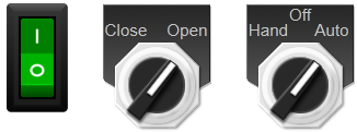
Selector switch tags allow you to add multi-position widgets such as Toggle buttons, mode selectors and Hand-Off-Auto switches to your applications.
The following widgets are available to Selector Switch tags:
